
I will talk about what pulse width modulation (PWM) is, how this technology is useful to electronics and robotics projects, and how to use it.
Why use PWM?
Exist a situation where it is needed control the power of a load, which can be a DC motor, a relay, a lamp, etc. It is possible to control a load linearly using a potentiometer or a rheostat.

The problems with this type of control are the loss of torque at lower speeds in the case of DC motors and the loss of power due to the potentiometer’s resistance. The PWM can give a soft start in motors and keep the torque at lower speeds. This technique is also used to control servomotors and dimmers (lamp controllers).
How does it work?
A PWM signal works like a switch turning on and off constantly; it is a continuous square wave. The signal’s amplitude will always be constant; therefore, the DC motor will always have the maximum torque. Since part of the time there is no current in the load, the efficiency is greater. You can control the width of the pulses in the signal.

There is a parameter called duty cycle, which says how long there is current in the load. Calculating the duty cycle in %, which is width of the pulse per the wave’s period.
DutyCycle=100\cdot\frac{Largura}{Período}
Some wave’s duty cycle.

Altering the pulse’s width also changes the average voltage. If a signal has 50% duty cycle, the average voltage will be half of the amplitude’s value.

PWM generators circuits
You can generate a PWM signal with a 555. To know more about this component, click on the button below:
 555Click here
This is an example of a circuit that controls the pulse’s width with a potentiometer.

The circuit was assembled on a protoboard.

Calculating the time when the signal stays in the “ON” level:
T_{H}=0.693\cdot R_{a}\cdot C1
- R_{a} is the value of the resistance from pin 8 to the middle terminal of the potentiometer.
The time when the signal stays in the “OFF” level:
T_{L}=0.693\cdot R_{b}\cdot C1
- R_{b} is the R2 value plus the other side of the potentiometer until the middle terminal.
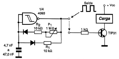
The period is the sum of the 2 times. Below we have another example of a PWM generator circuit.

 is, how this technology is useful to electronics and robotics projects, and how to use it.)