
The common base is little known configuration for amplifiers using BJT. This type is used in high frequencies.
Link to the post about BJT’s operation.
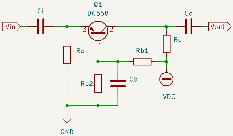
Common base amplifier with NPN transistor

First, the transistor must be defined, in this project was used the BC548, which has many datasheets that can be found in this link. The supply voltage (VCC) was arbitrarily chosen as 15V. While input impedance, which must have a low value, was considered as 50Ω.
Defining emitter and collector resistors
The value of resistance on emitter (Re) was chosen as 2.2kΩ. Below is the equation of input impedance for common base amplifiers.
Zi=\frac{Re\cdot r_{e}}{Re+r_{e}}
50=\frac{2200\cdot r_{e}}{2200+r_{e}}
r_{e}=51.1\Omega
Finding the current emitter value.
r_{e}=\frac{V_{T}}{I_{E}}
I_{E}=\frac{26m}{51,1}=0.508mA
Calculating emitter (V_{E}) and base (V_{B}) voltages. Knowing that base-emitter voltage (V_{BE}) is 0.7V.
V_{E}=Re\cdot I_{E}=22k\cdot 0.508m=1.1176V
V_{BE}=V_{B}-V_{E}
V_{B}=1.876V
Collector voltage value (V_{C}) is arbitrary. However, it must be higher than V_{B}, otherwise the circuit won’t amplify the signal. As was explained in the first part of BJT polarization. I choose V_{C} as 7.5V, half of VCC. The collector current (I_{C}) and emitter current (I_{E}) can be considered as equal.
I_{E}\simeq I_{C}=0,508mA
Rc=\frac{VCC-V_{C}}{I_{C}}=14.76k\Omega
The closest commercial value is 15kΩ. In common base, output impedance (Z_{o}) has the same value of Rc.
Defining base resistors
Using voltage divider equation.
V_{B}=\frac{Rb2\cdot VCC}{Rb2+Rb1}
1.876=\frac{Rb2\cdot 15}{Rb2+Rb1}
Rb1=6.996\cdot Rb2
Considering Rb2 as 1kΩ, Rb2 is equal to 6.996kΩ. The closest commercial available value is 8.2kΩ.
Calculating capacitors
Equation to calculate input capacitor value.
f=\frac{1}{2\pi \cdot Ci\cdot Zi}
Input impedance Zi is 50Ω and frequency arbitrary value is 100kHz.
Ci=\frac{1}{2\pi fZi}=\frac{1}{2\pi \cdot 10^{5}\cdot 50}=31,83nF
The closest commercial available value is 47nF, which gives a cutoff frequency of 67.7kHz. Can also use one of 33nF. Designing output capacitor, where output impedance (Zo) is 15kΩ.
Co=\frac{1}{2\pi fZo}=\frac{1}{2\pi \cdot 10^{5}\cdot 15000}=106pF
The commercial value is 100pF. Calculating bypass capacitor Cb, cutoff frequency was arbitrarily chosen as 500kHz.
Cb=\frac{1}{2\pi fRb2}=\frac{1}{2\pi \cdot 5\cdot 10^{5}\cdot 10^{3}}=318pF
The commercial value is 270pF, which gives a cut frequency of 589.4kHz.

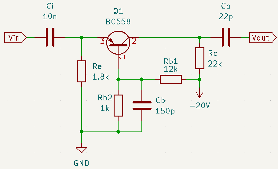
Common base amplifier with PNP transistor
The used BJT is BC558, whose datasheets are on this link. Input impedance (Zi) is 50Ω again and supply voltage is -20V.
Calculating resistors
Re was chosen as 1.8kΩ.
Zi=\frac{Re\cdot r_{e}}{Re+r_{e}}
50=\frac{1800\cdot r_{e}}{1800+r_{e}}
r_{e}=51.4\Omega
Finding collector current. With PNP transistor, it has a negative value.
r_{e}=\frac{V_{T}}{\left| I_{E}\right|}
\left| I_{E}\right|=\frac{26m}{51.4}=0.506mA
Calculating voltages on BC558’s terminals. Since transistor is PNP, voltages must be negative.
V_{E}=Re\cdot I_{E}=-0.9108V
V_{BE}=V_{B}-V_{E}
-0.7=V_{B}+0.9108
V_{B}=-1.6108V V_{C} value is arbitrarily, but it must be lower than V_{B}, because it’s a PNP amplifier. V_{C} is equal to -10V, half of supply voltage. Calculating collector resistance.
Rc=\frac{VDC-V_{C}}{I_{C}}
I_{E}\simeq I_{C}=-0.506mA
Rc=\frac{-20+10}{-0.506m}=19.7k\Omega
Commercial value of Rc is 22kΩ and it’s equal to output impedance Zo. Calculating base resistors.
V_{B}=\frac{Rb2\cdot VCD}{Rb2+Rb1}
-1.6108=\frac{-20\cdot Rb2}{Rb2+Rb1}
-1.6108\cdot Rb1=-18.3892\cdot Rb2
Arbitrary value: Rb2=1kΩ.
Rb1=11.41k\Omega
Rb1 commercial value is 12kΩ.
Calculating capacitors
Defining input capacitor (Ci) arbitrarily as 10nF and calculating cutoff frequency f.
f=\frac{1}{2\pi \cdot Ci\cdot Zi}=\frac{1}{2\pi \cdot 10^{-8}\cdot 50}=318.3kHz
Calculating output capacitor Co.
f=\frac{1}{2\pi \cdot Co\cdot Zo}
Co=\frac{1}{2\pi \cdot 318.3\cdot 10^{3}\cdot 22\cdot 10^{3}}=22.7pF
The commercial value is 22pF. Designing the bypass capacitor Cb, cutoff frequency is 1MHz.
Cb=\frac{1}{2\pi f\cdot Rb2}=\frac{1}{2\pi \cdot 10^{6}\cdot 10^{3}}=159pF
Cb commercial value is 150pF. The complete amplifier below.
Common base amplifiers’ video
The common base amplifier must receive a signal with very low amplitude, otherwise the output signal will be saturated and will have a different shape from input signal. Blue=input and yellow=output.
