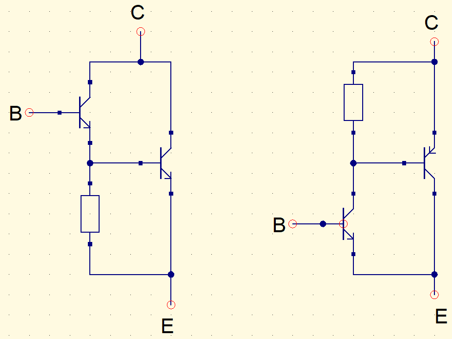
The Darlington and Sziklai pairs are settings with BJT transistors. The comparison between both and some circuits are shown in this post.
If you don’t know how a BJT transistor works, click the link below before continuing.
How BJT transistor works?Click here
Darlington pair

Input current enters on (B) base of T1 transistor. The emitter’s current, which is the sum of base and collector currents, goes to T2’s base, amplifying the current on T2. The pair’s gain (h_{FE} ou \beta) is:
\beta=\beta_{T1}\cdot\beta_{T2}+\beta_{T1}+\beta_{T2}
Where \beta_{T1} and \beta_{T2} are the individual gains of T1 and T2, respectively. Darlington combination is used in applications that require high signal amplification and high power component control.


Circuit examples

The following video shows the circuits in a protoboard. LED turns on when the sensor is touched, note brightness difference between the LEDs.
This other circuit uses a Darlington setting with S9012H pnp transistor, whose datasheet is here. It has a KY-003 Hall effect sensor module, which when detects a magnetic field, the buzzer beeps and the small LED turns on.


Sziklai pair

This configuration used a npn and a pnp. This is pair’s gain formula, considering \beta_{T1} as the gain of BJT T1, which collector is linked to T2’s base.
\beta=\beta_{T1}\cdot\beta_{T2}+\beta_{T1}
In some cases, for simplification, it’s considered that the gains of Darlington and Sziklai pairs are simply the product of transistors’ gains. If you put a capacitor on feedback, linking one’s base to another’s collector, the circuit becomes an oscillator.


A video showing the operation of both projects.
Comparing Darlington and Sziklai configurations
One of the advantages of Sziklai pair is that needs a base-emitter voltage (V_{BE}) between 0.3V and 0.7V to go into saturation, the same range as a single BJT. While Darlington configuration requires 1.2V. As a result, Darlington dissipates more power and has a slower response time. On the other hand, Sziklai’s gain is lower.


