
In this post, it’s shown the operation of the noninvasive current sensor SCT-013 and how to use it with Arduino.
How the current sensor SCT-013 works?
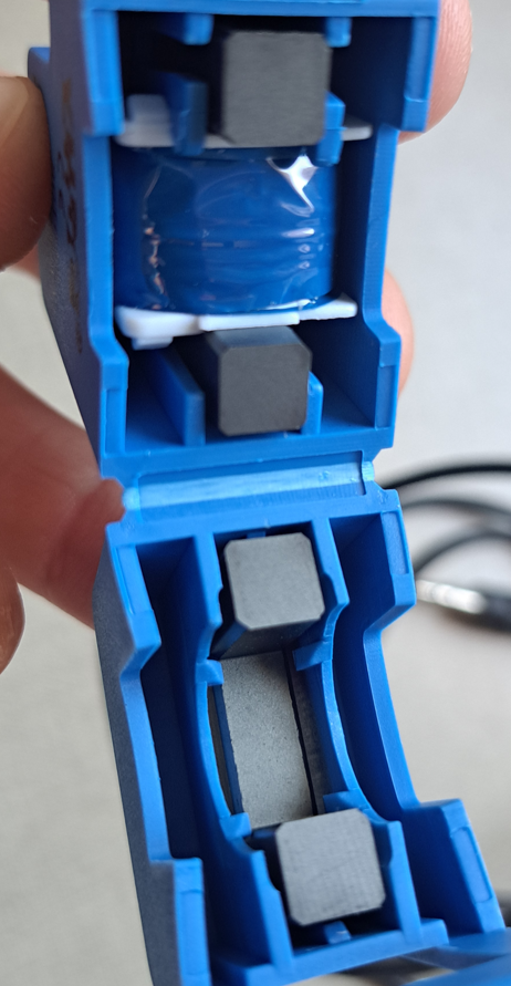
The great advantage of non-invasive current sensor is that you don’t need to interrupt the circuit to make the measurement. Inside the current sensor, there is a magnetic circuit, a coil with a divided magnetic core.
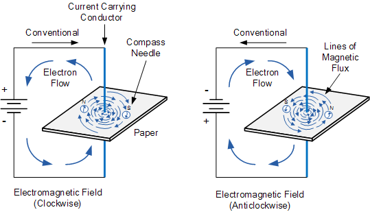
The electric current produces a magnetic field, following the right hand rule. If the current is alternate, its direction changes in a determined frequency, consequently, the generated magnetic field’s direction also changes.
On SCT-013 sensor, the core is around the cable, whose electrical current is being measured. The variable magnetic field of current (Ip) induces a voltage on the sensor’s coil, producing a secondary current (Iout), which is proportional to Ip. This is the current transformer principle.
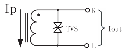
What is the TVS on circuit? It’s a bidirecional TVS diode, whose function is to protect the circuit against voltage peaks during inductor’s discharge. This sensor can only measure alternate current’s RMS value up to 100 A.
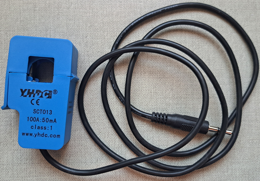
Other SCT-013 features:
- Temperature range: from -25ºC(-13ºF) to 70ºC(158ºF).
- Non-linearity (lack of linear proportion between input and output): 3%.
- Output current: from 0 up to 50 mA.
- Since output current (Is) is 50 mA, for a primary current (Is) of 100A, the winding ratio is 1:2000, by that, there are 2000 turns on sensor’s coil and it’s considered that the cable under measure is the primary winding (Np) of the current transformer. Below is the ideal transformer’s formula.
Testing current sensor with Arduino
Interface between SCT-013 and Arduino
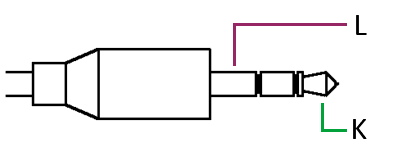
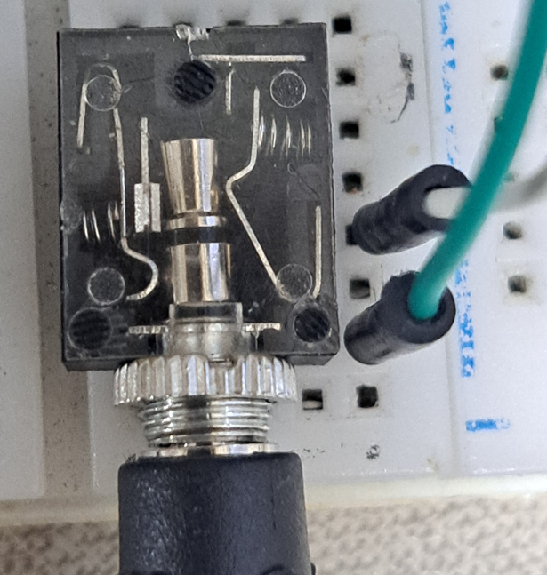
Arduino’s analog input can only read values from 0 to 5V. Therefore, its necessary to condition the signal to avoid damage to Arduino. For this purpose, must use the jack J-2 stereo female, to connect SCT-013’s P2 plug with the interface circuit.
Calculating maximum current peak (I_{peak}) which sensor can measure:
I_{peak}=I_{RMS}\times\sqrt{2}=100\times\sqrt{2}=141,4A
Using the relation between current and number of turns, assuming I_{p}=141,4A.
I_{S}=0,0707A=70,7mA
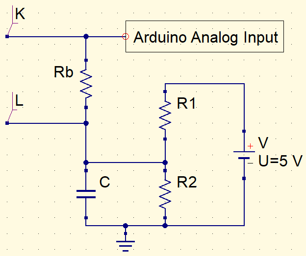
Since Arduino analog input can only read values from 0 to 5V, the maximum voltage on the load resistor (Rb) must be 2.5V. Therefore:
It’s appropriated to use the commercial value of 33Ω. R1 and R2 resistors must be equal, so that the offset voltage can be 2.5V, in this way, there won’t be negative values on Arduino input. The arbitrarily chosen value for both was 10kΩ. The function of capacitor C is to transform the sinusoidal signal in a more linear one with a ripple. C’s value is 10μF.
Finding calibration value
The calibration value is important for current transformer to properly measure current and this value must be added on algorithm. Calibration value is the division of number of turns on secondary winding (in this case 2000) by the load resistor Rb.
However, if the maximum current you want to read is lower than 100A, the resistor Rb and calibration value must be different. In my case, I determined the maximum RMS current as 5A. Using calculations previously shown, Rb’s commercial value is 680Ω and calibration value is 2.941.
Materials complete list, circuit and code
- SCT-013 current sensor.
- Arduino Uno.
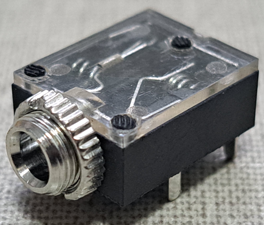
- Jack J-2 stereo female.
- 10μF x 16V electrolytic capacitor.
- 3 resistors: 2 10kΩ and one 680Ω.
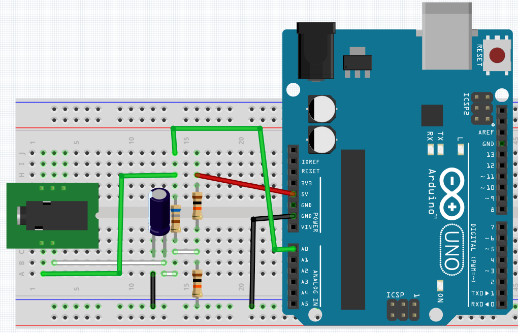
The circuit in protoboard and algorithm for test, respectively. It’s necessary to download the “EmonLib.h” library, whose link is here.
#include <EmonLib.h> //Library name.
EnergyMonitor SCT013; //sensor declaration.
int sensor = A0;
int voltage = 127;
void setup() {
Serial.begin(9600);
SCT013.current(sensor,2.941); //(input pin, calibration value);
}
void loop() {
double Irms = SCT013.calcIrms(2000);//library function to calculate RMS current.
Serial.print("Corrente = ");
Serial.print(Irms);
Serial.println(" A");
delay(400);
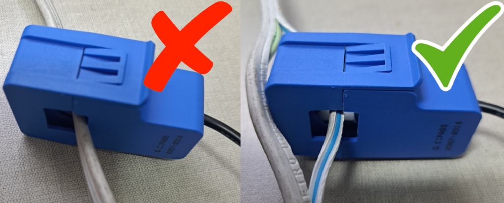
}Important: SCT-013 measures only the alternate current of a conductor at a time, if you measure 2 or more conductors, the magnetic fields will cancel each other and the sensor will measure the current as zero.
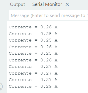
What should appear on Serial screen.
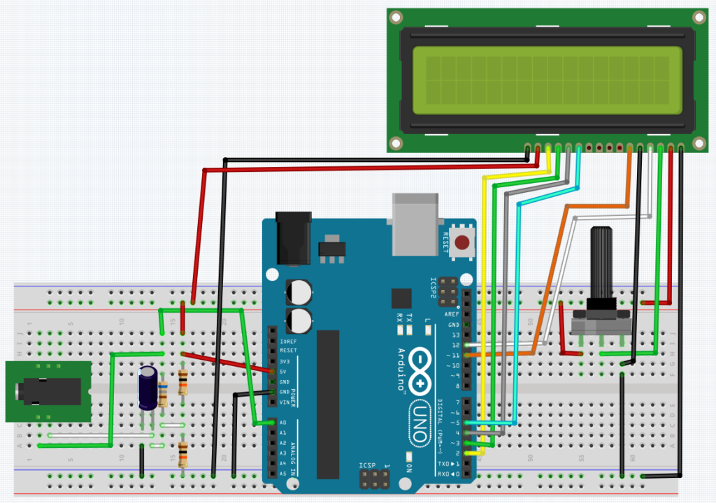
Adding a LCD display
This is the same project, but with a LCD to show RMS current.
To know how to use LCD on Arduino, click on the following link.
Arduino tutorial (Part 7, LCD display)Click here
The code and demonstration video, respectively.
#include <EmonLib.h>
#include <LiquidCrystal.h>

LiquidCrystal lcd(12,11,5,4,3,2);
EnergyMonitor SCT013;

int sensor = A0;

void setup() {
  lcd.begin(16,2);
  lcd.clear();
  SCT013.current(sensor,2.941);//2.941
}

void loop() {
  lcd.setCursor(0,0);
  double Irms = SCT013.calcIrms(2000)-0.01;//This substraction is to make calibration //with code.
  lcd.print("Irms=");
  lcd.print(Irms);
  lcd.print("A");
  delay(100);
}
I found out that research about how to use graphic LCD on Arduino will take longer than expected. However, I will publish a post in the future.