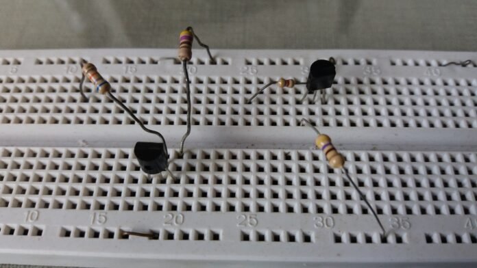
Polarization is important to design circuits with transistors. In this post, will be shown how to polarize the BJT transistor in CC mode.
Operation modes
As I already explained in the post about operation of BJT transistor, exist three operation modes, click in the button below to read to post.
To polarize the BJT transistor, you can use the diode pair model, as showed below. On the left is NPN and on the right is PNP.

In the cutoff operation mode, the base-collector (BC) and base-emitter (BE) junctions must be in reverse polarization. The emitter voltage (V_E) must be bigger than the base voltage (V_B). And the later must be smaller than collector voltage (V_C). When the transistor is PNP, the base voltage must be bigger than collector and emitter voltages.
NPN: V_C>V_B and V_E>V_B
PNP: V_B>V_C and V_B>V_E
In saturation mode, the base-collector (BC) and base-emitter (BE) junctions must be in direct polarization. Therefore, the base voltage (V_B) must be bigger than the voltages in collector (V_C) and emitter (V_E). In the PNP, V_B must be smaller than V_C and V_E.
NPN: V_B>V_C e V_B>V_E
PNP: V_C>V_B e V_E>V_B
In active mode, the base-collector junction must be in reverse polarization, while the base-emitter junction must be directly polarized. Therefore, the collector voltage (V_C) must be bigger than the base voltage (V_B), the later by its turn must be bigger than the emitter voltage (V_E). While in the PNP, V_E must be bigger than V_B, which needs to be bigger than V_C.
NPN: V_C>V_B>V_E
PNP: V_E>V_B>V_C
CC polarization
Let’s polarize the BJT transistor to make circuit projects. This is an inverter with NPN. The output must have the inverse digital signal of input.
 We have to calculate the resistors Rc and Rb. First let’s look at datasheet of BC548B, can be found here, to see the current gain (h_{FE}) and the collector current when stays in saturation I_{C(SAT)}.

Considering h_{FE} as 200 and I_{C(SAT)} as 10 mA. If you wish, can choose the values of 450 and 100 mA respectively. Calculating Rc, considering Vce_{(sat)} as 0.25 V.
R_C=\frac{Vcc-Vce_{(sat)}}{I_{C(max)}}
R_C=\frac{5-0,25}{10m}
R_C=475 \Omega
We have to choose commercial values to build the circuit. Therefore, Rc value is 470 Ω. Calculating base current I_B.
I_B=\frac{I_{C(sat)}}{h_{fe}}
I_B=\frac{10m}{200}
I_B=0,5\cdot 10^{-4} A
Discovering the value of Rb.
R_B=\frac{V_{in}-V_{BE}}{I_B}
R_B=\frac{5-0,7}{5\cdot 10^{-5}}
R_B=86 k\Omega
Let’s use the commercial value of 82 kΩ. The input and output signals must be like in the figure below. The blue above is the input and the yellow is the output.

Let’s design a PNP inverter. In the BC558`s datasheet, you can find the h_{FE} as 110 and I_{C(SAT)} as -10 mA.

Using the same equations in the previous example, the commercial values of Rc and Rb are respectively 470 Ω and 4.7 kΩ. The input and output must be equal in the previous example.

In the next part, I will show some project examples applying CC polarization.


