Exist other circuit theorems in addition to Thévenin and Norton. Are shown in this post: Maximum power transfer, Millman and Substitution.
Maximum power transfer theorem
Exist situations, where it is necessary to know the value of necessary resistance or impedance in a part of circuit to transfer as much power as possible to that load. This is an application of Thévenin’s theorem, which have already been showed in a post.
Superposition, Thévenin and NortonClick here
The circuit below is used as example. We have to calculate value of RL so that maximum power is transferred to this resistor.

First we have to find Thévenin resistance and voltage. Method have already been explained in post about the subject, whose link is above. In this example, Thévenin resistance Rth and voltage Vth are respectively.
Rth=4,04k\Omega
Vth=9,77 V
To have maximum power transfer, RL must be equal to equivalent Thévenin resistance of circuit.
 Calculating transferred power to RL.
P_{L}=I_{L}^{2}\cdot R_{L}=(\frac{V_{Th}}{2R_{Th}})^{2}\cdot R_{Th}=\frac{V_{Th}^{2}}{4R_{Th}}
Power value.
P_{L}=5,906mW
Millman theorem
The 2 following circuit theorems are little known. Millman theorem determines that many voltage sources in parallel are equivalent to only one source.

How to convert many sources in one? First, all voltage sources must be converted in current sources. It has already been demonstrated how to do this in post “Circuit analysis (Part 1)“.

In this conversion, resistance become conductance G. This is the inverse of resistance, whose value is in Siemens (S).
G=\frac{1}{R}
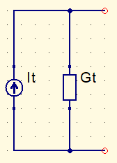
Next step is to convert all sources in only one current source.

It=I_{1}+I_{2}+I_{3}
Gt=G_{1}+G_{2}+G_{3}
Finally, convert the equivalent current source It in a voltage source. Conductance becomes resistance again.

R_{eq}=\frac{1}{Gt}=\frac{1}{G_{1}+G_{2}+G_{3}+...+G_{N}}
V_{eq}=\frac{It}{Gt}=\frac{\pm V_{1}G_{1}\pm V_{2}G_{2}\pm V_{3}G_{3}\pm ...\pm V_{N}G_{N}}{G_{1}+G_{2}+G_{3}+...G_{N}}
R_{eq}=\frac{1}{\frac{1}{R_{1}}+\frac{1}{R_{2}}+\frac{1}{R_{3}}+...+\frac{1}{R_{N}}}
This theorem also can be used to find maximum power transfer to a load.
Substitution theorem
According to book Circuit Analysis, by Robert L. Boylestad, 12th edition, this theorem claims:
If current which crosses a branch of a DC bilateral circuit and voltage between terminals in the same branch are known, this branch can be replaced by any component combination which keep unchanged voltage and current associated to chosen branch.
This theorem is a form to simplify electric circuits, replacing one circuit part by a voltage or current source. Can be used with other circuit theorems.


