The rotary encoder looks like a potentiometer, but the operation is completely different. How it works and how to use it in Arduino are today’s subjects.
How rotary encoder works?
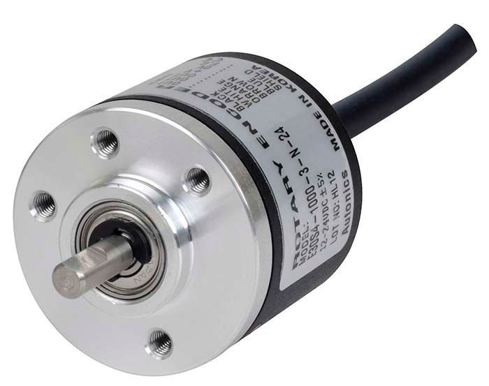
It’s an electromechanical component, converts rotational movement in square wave electric pulses that can be read by microcontrollers. Inside this component, there’s an opaque disk with grooves that allow light passage.
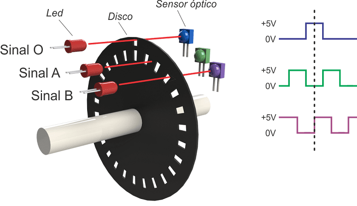

output pulses. Source: UWE.
In one disk’s side, there’s a light source, usually an infrared LED. In the opposite side, there is one or more light sensors, usually phototransistors, and an electronic circuit to transform sensor’s electric signal in square wave.

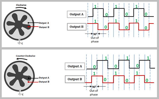
The encoder can send feedback signals for control systems, showing information like speed, rotation direction, position and angle.
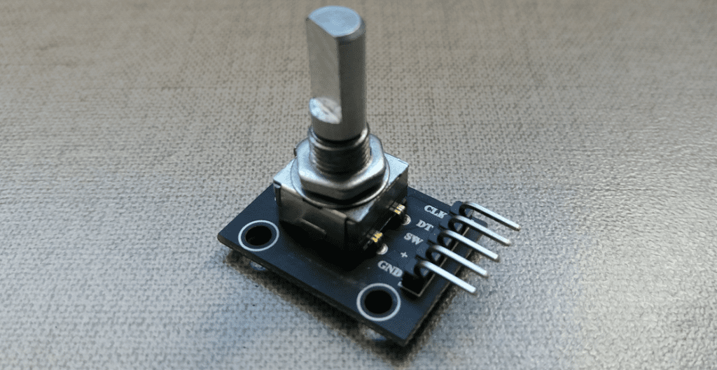
The KY-040 encoder
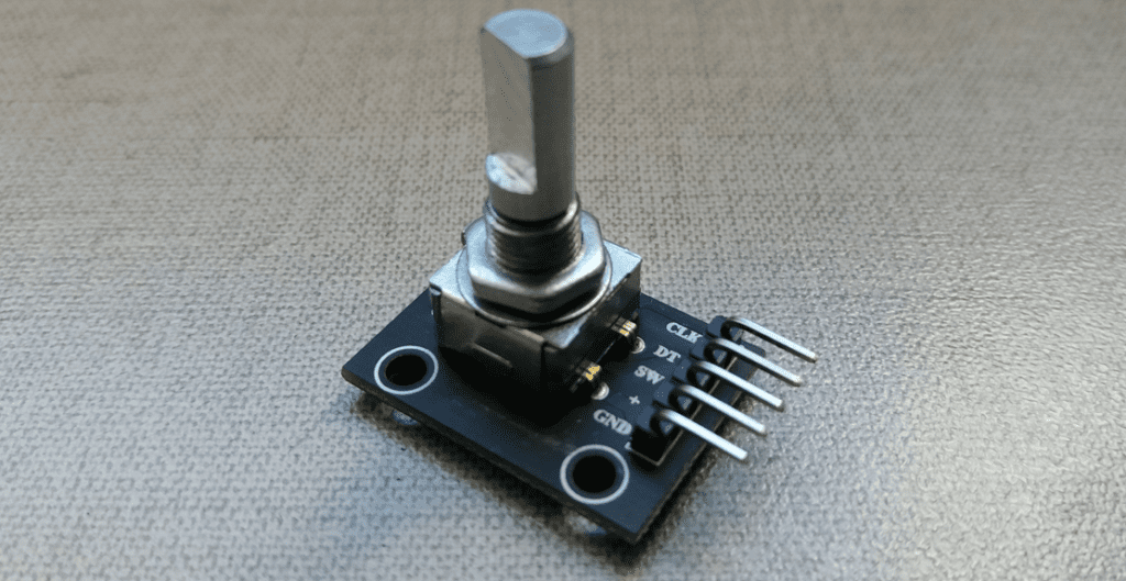
The KY-040 has 2 phototransistors to detect rotation direction and a button that is pressed when you press the rotation shaft. Allows continuous rotation with a resolution of 20 pulses/revolution. It’s operation voltage is 5V, with maximum current of 10 mA.

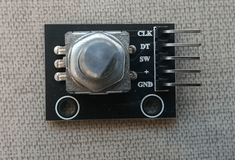
KY-040’s pins:
- + and GND are power supply and ground respectively.
- SW: signal that indicates if the button is pressed. Is on “low” level when the shaft is pressed.
- DT: where direction pulses come from.
- CLK: is the clock, signal that coordinates chip’s functions.
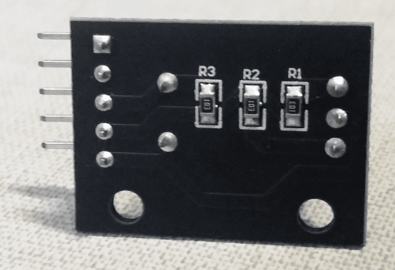
Using KY-040 with Arduino
Testing the encoder
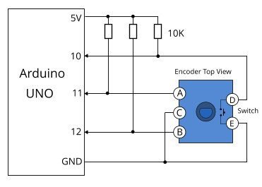
To use this rotative encoder, it’s much easier download the library “RotaryEncoder.h”, whose link is here. For this test, are necessary only the KY-040 module, 1 Arduino Uno and wires to link both.
- CLK pin is linked to GND pin.
- + is connected to 5 V.
- SW is linked to Arduino’s digital pin 7.
- DT with analog pin A2.
- CLK with analog pin A3.
The code below.
#include <RotaryEncoder.h>
RotaryEncoder encoder(A2,A3); //connection pins.
int valor=0; //variable for encoder's button.
int newPos=0;
void setup() {
pinMode(7,INPUT);
Serial.begin(9600);
Serial.println("Turn the encoder...");
}
void loop() {
//O botão foi pressionado?
valor=digitalRead(7);
if(valor != 1){
Serial.println("Pressed button");
while(digitalRead(7)==0)
delay(10);
}
//Read encoder's information
static int pos=0;
encoder.tick();
int newPos=encoder.getPosition();
//If the position was altered, shows the value on Serial monitor.
if(pos != newPos){
Serial.print(newPos);
Serial.println();
pos=newPos;
}
}
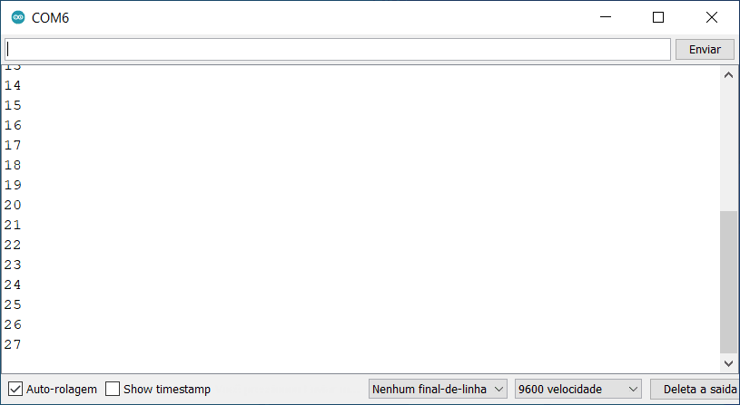
Initially, the Serial monitor must show the phrase “Turn the encoder…”, turning in one direction must appear positive numbers, and negative in the opposite direction. If press the button, appears the message “Pressed button”.

As you spins the encoder in one direction, the pos variable must increase or decrease it’s value.
Project
In this project are added 2 sets of 6 LEDs in series and one yellow LED with a 470 Ω resistor, this one indicates if the button was pressed.
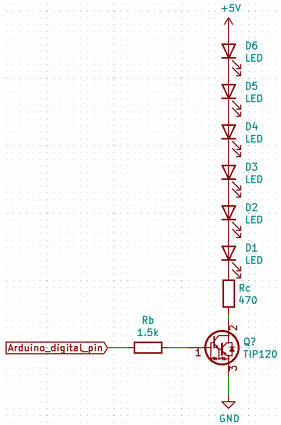
Materials list:
- 1 Arduino Uno.
- Protoboard.
- 1 KY-040 encoder.
- 13 LEDs, 6 of each color and 1 with a different color.
- 2 TIP 120.
- 5 resistors, 3 of 470 Ω and 2 of 1.5 kΩ.
- Printed circuit board and/or terminal bridge.
The code below.
#include <RotaryEncoder.h>
RotaryEncoder encoder(A2,A3);
int redPin=9;
int yellowPin=5;
int greenPin=6;
int button=7;
int valor=0;
int newPos=0;
void setup() {
pinMode(button,INPUT);
pinMode(redPin,OUTPUT);
pinMode(yellowPin,OUTPUT);
pinMode(greenPin,OUTPUT);
Serial.begin(9600);
}
void loop() {
if(digitalRead(button)==LOW){
digitalWrite(yellowPin,HIGH);
}else{
digitalWrite(yellowPin,LOW);
}
static int pos=0;
encoder.tick();
int newPos=encoder.getPosition();
//If positon is altered, shows value on Serial.
if(pos != newPos){
Serial.print(newPos);
Serial.println();
if(pos<newPos){ //Verify which direction is spinning.
digitalWrite(redPin,HIGH);
digitalWrite(greenPin,LOW);
}else if(pos>newPos){
digitalWrite(redPin,LOW);
digitalWrite(greenPin,HIGH);
}
pos=newPos;
}
}
The video below shows the CLK and DT outputs and how the project must work.

