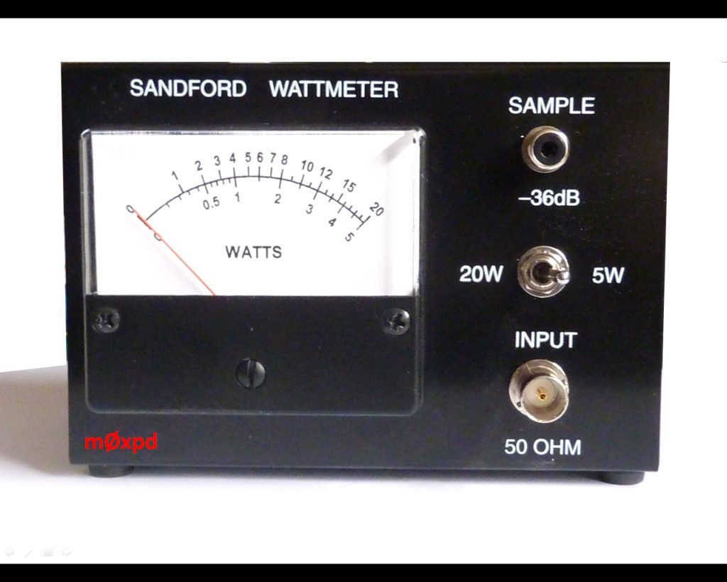
Fulfilling the request, This post’s subject is wattmeter operation. An instrument that measures provided or dissipated power in a circuit.
Electrodynamic wattmeter
Operates with a moving coil, the voltage inductor, and 2 static coils, connected in series, voltage inductors. The moving or pressure coil is linked to a pointer with a spiral spring. The current fixed coils generate a magnetic field when receiving electric current. When current passes through the moving inductor, a torque is generated on it and the pointer moves.
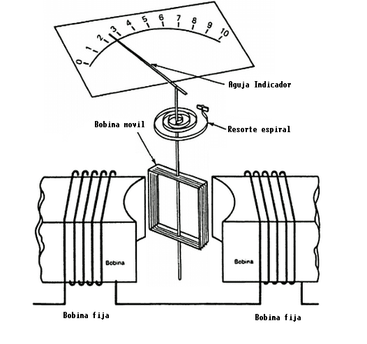

This type of wattmeter can measure powers in DC and AC. It’s also used in calibration due to high degree of precision.
Measurement in direct current
The equation of deflection torque T_{d} on the moving inductor’s pointer.
T_{d}=i_{c}i_{p}\frac{\delta M}{\delta \theta }
- i_{c} and i_{p} are the instantaneous currents on fixed and voltage inductors respectively.
- \frac{\delta M}{\delta \theta } is the rate of pointer deflection related to \theta angle.
The restorative torque T_{c} produced by the spring is:
T_{c}=K\theta
- K is the spring constant in Newtons/meter (N/m).
When the power is being measured, the torques T_{d} and T_{c} are balanced and become equal.
T_{d}=T_{c}
i_{c}i_{p}\frac{\delta M}{\delta \theta }=K\theta
The deflection angle becomes:
\theta =\frac{(i_{c}i_{p}\frac{\delta M}{\delta \theta })}{K}
Measurement in alternate current
Voltage value in the moving coil.
v=V_{rms}\sqrt{2}\cdot sen(\omega t)
If the resistance linked to voltage inductor is too high, it can be considered purely resistive. In this case,
i_{p}=\frac{v}{R}
i_{p}=\frac{V_{m}\cdot sen(\omega t)}{R}
i_{p}=Ip_{m}\cdot sen(\omega t)
If the current that passes through fixed inductors (i_{c}) is delayed in relation to i_{p}, the equation becomes:
i_{p}=Ip_{m}\cdot sen(\omega t-\phi )
While i_{c}:
i_{c}=Ic_{m}\cdot sen(\omega t)
Deflection torque equation in AC, after solving an integer.
T_{d}=Ic_{m}Ip_{m}\cdot cos\phi \cdot \frac{\delta M}{\delta \theta }
Deflection angle.
\theta =\frac{Ic_{rms}Ip_{rms}}{K}\cdot cos\phi \cdot \frac{\delta M}{\delta \theta }
Measurement errors
The factors that cause errors in measure are: inductance and capacitance of pressure coil, mutual inductance between the coils, stray magnetic field, temperature and edgy currents.
If an electrodynamic wattmeter made for 50 Hz operates in 60 Hz, or vice-versa, edge current values will change, which can cause errors in measures.
Induction wattmeter
This type can only be measured in AC. Consists in two electromagnets with laminated core made of steel silicon: shunt and series magnets. Between these electromagnets, there is a thin disk of aluminum, the aluminum disk receives variable magnetic field and induced current appears on the disk. The induced current in the presence of a magnetic field produces a torque on disk, that is connected to a pointer.
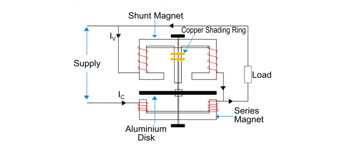

This type can only be used when the frequency, voltage and temperature are constant. However, this wattmeter can only operate in the frequency that was designed. In the other hand, Don’t suffer the effects of external magnetic fields.
Phase diagram
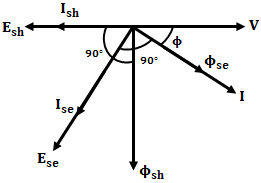
The resulting torque T is proportional to generated voltage V and current I and to power factor cos\phi.
T_{d}\propto VI\cdot cos\phi
Digital wattmeter
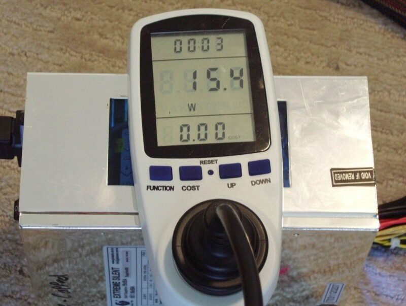
Measures instantaneous voltage and current many times per second. These 2 measures are multiplied by a microprocessor and the result is shown by a LCD display. Some digital wattmeters also can measure power factor, active and passive powers, energy consumption in KWh, frequency, peak and RMS values.


