
This is the post’s second edition. It’s shown one more project to control servomotors with a joystick, using another method.
In this tutorial, it is shown how to use the joystick module in Arduino to make projects. This module is similar to the model found in Playstation controls.
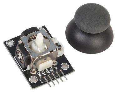
How does the joystick work?
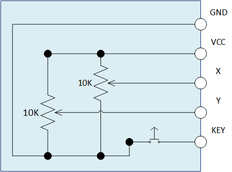
The shield has two potentiometers, these give information about joystick’s position.

Also has a button, to be pressed must press the top of joystick without being inclined.

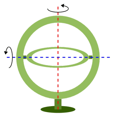
Taking out the pin. Note that one potentiometer is connected to the white stem, it stays in the middle of two arcs linked to another potentiometer. This is the 2 axes gimbal mechanism, which allows two potentiometers to move at the same time.
The pins VRx and VRy are analog outputs of potentiometers and SW is the button’s output.

Test with joystick module
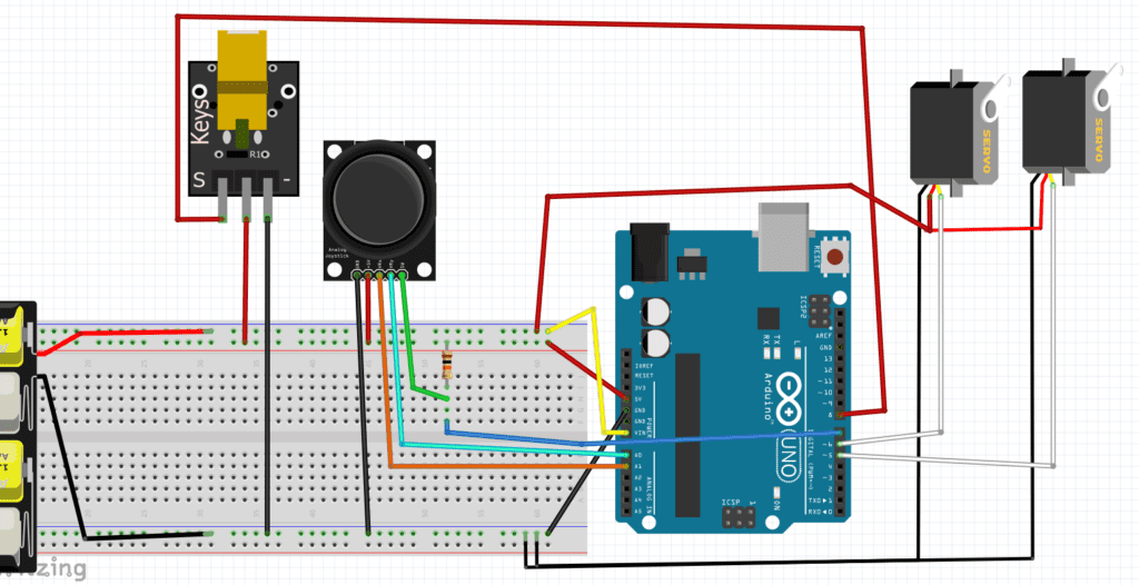
The module’s connection with Arduino.
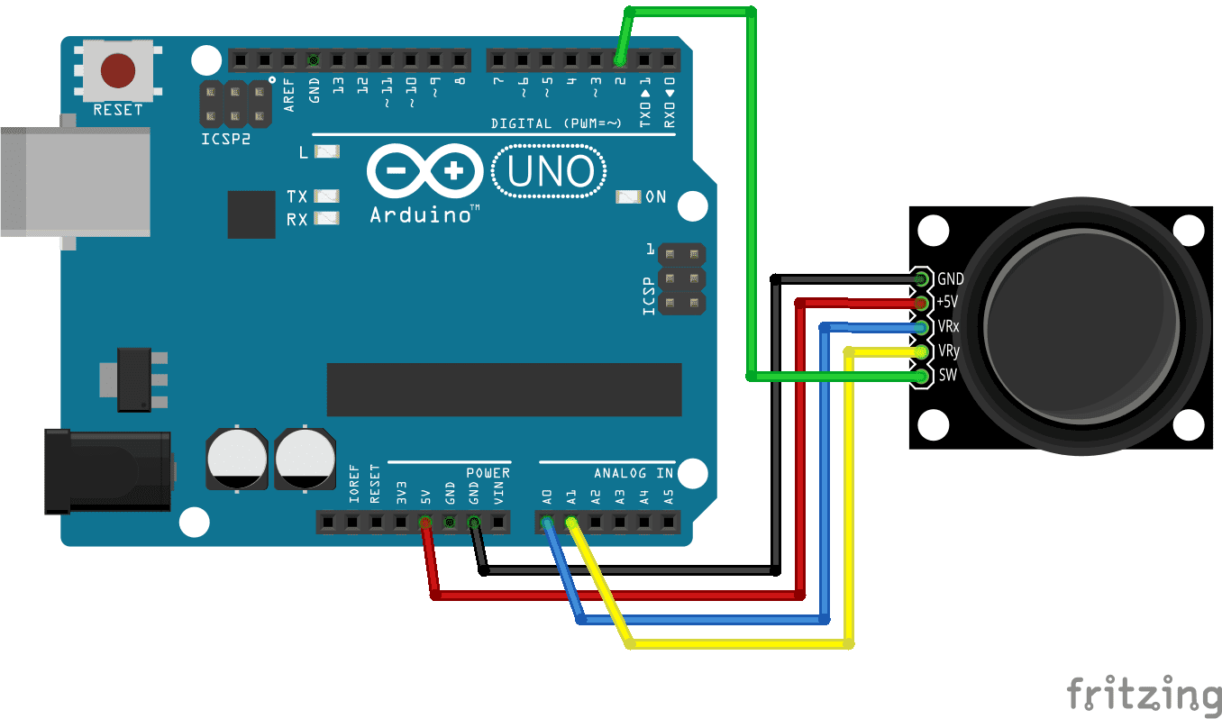
This is the code, when moving the joystick, analog values “xValue” and “yValue” must change in the Serial window.
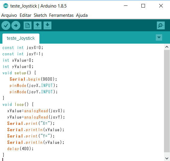
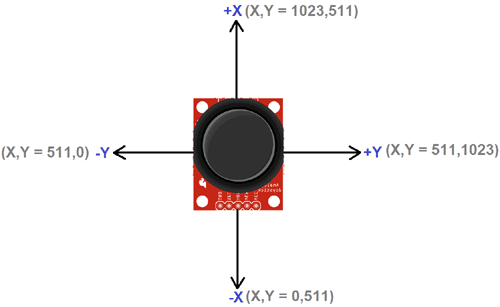
The “xValue” and “yValue” values change from 0 to 1023 depending on joystick’s position, representing x and y axes. These are x and y coordinates that appear on Serial screen in relation to the position. In practice, there is some variation.
Controlling LEDs and servomotors
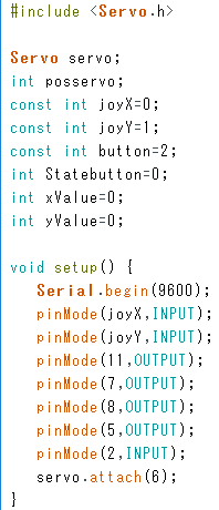
In this project, the joystick controls 4 LEDs of different colors and a servomotor. Each direction for which it is inclined, a LED turns on and servomotor turns a step, for each diagonal direction, 2 LEDs turn on.
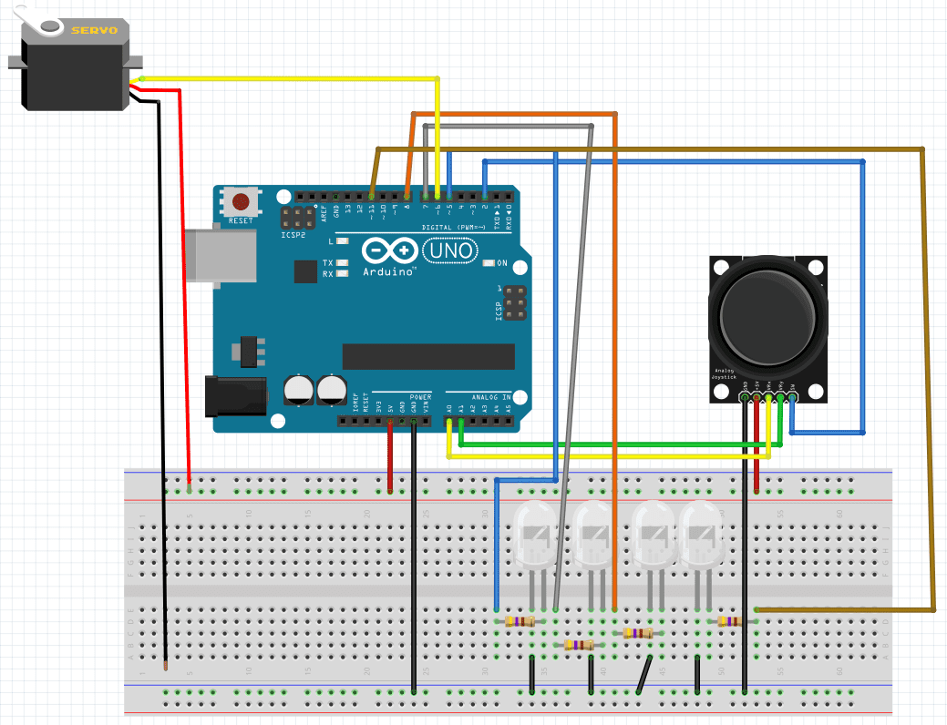
To shorten the code, pins for LEDs don’t have names, were simply called 5, 7, 8 and 11. Note the declarations like “pinMode(11,OUTPUT);” and commands like “digitalWrite(7,HIGH);”.
Using libraries
This is an example of a program using a library for the module, here is the link. This example comes from the source to show how the library works.

This declaration defines pins of x, y axes, and button respectively. Here were defined as analog pins 0 and 1, the button’s input is digital 4.

This command print values of x and y axes. The z value shows if a button is pressed, in my case, false when pressed and true when released. The 0 and 100 are minimum and maximum values of coordinates of axes.

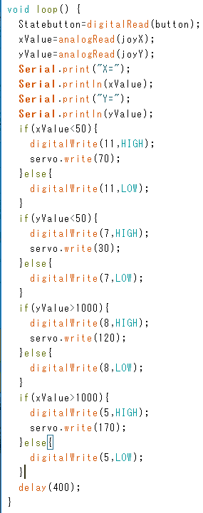
2 servomotors and laser control with joystick
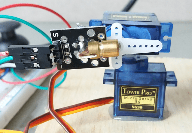
In this project, the joystick’s potentiometers control 2 servomotors and the button controls a laser module. It’s pressed once, the laser turned on and pressed again and the laser is turned off.
The algorithm that must be used. The button control was taken from an example on Arduino program itself. The name is Debounce and it’s on Digital.
#include <Servo.h>

int laserPin=8;
int buttonjoy=7;

int laserstate=HIGH; // the current state of the output pin.
int buttonstate;       // the current reading from the input pin.
int lastbuttonstate=LOW; // the previous reading from the input pin.

//Both variables in milliseconds and must be classified to store more memory //than int.
unsigned long lastDebounceTime = 0;  // // the last time the output pin was //toggled
unsigned long debounceDelay = 50;    // the debounce time; increase if the //output flickers

//The servos.
Servo servoH;
Servo servoV;

int angle1,angle2;

void setup() {
  pinMode(laserPin,OUTPUT);
  pinMode(buttonjoy,INPUT);
  digitalWrite(laserPin,laserstate);
  servoH.attach(5);
  servoV.attach(6);
  servoH.write(90);
  servoV.write(90);
}

void loop(){
  angle1=map(analogRead(A0),0,1023,0,180);
  angle2=map(analogRead(A1),0,1023,0,180); //With map function, the values //of potentiometer analog input from 0 to 1023 are mapped to stay between 0 //and 180 degrees.
  servoH.write(angle1);
  servoV.write(angle2);
  delay(50);
  int readbutton=digitalRead(buttonjoy); // read the state of the switch //into a local variable.
  if(readbutton!=lastbuttonstate){ // If the switch changed, due to noise or //pressing.
     lastDebounceTime = millis(); // reset the debouncing timer.
  }
  if((millis()-lastDebounceTime)>debounceDelay){ // whatever the reading is //at, it's been there for longer than the debounce
    // delay, so take it as the actual current state.
    if(readbutton != buttonstate){ // if the button state has changed.
      buttonstate=readbutton;
      if(buttonstate==HIGH){  // only toggle the laser if the new button //state is HIGH.
        laserstate = !laserstate; //! means negation.
      }
    }
  }
  digitalWrite(laserPin,laserstate); // set the laser on current state.
  lastbuttonstate=readbutton;  // save the last reading.
}
The SG90 microservos are the most suitable for this project. If you use bigger servomotors, you can have the risk of overshoot, as shown in the video below.
https://youtube.com/shorts/hQZJ9EMCLSQ?feature=share
The video of project working.
