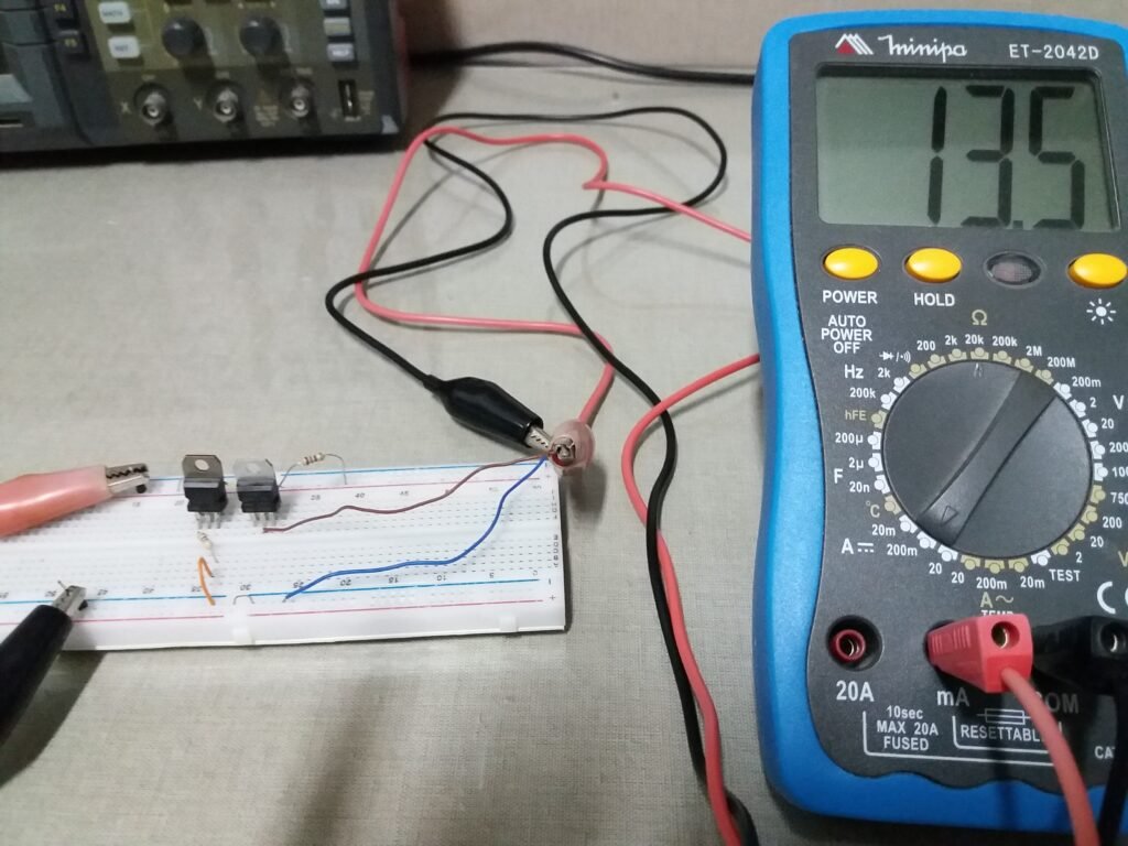
The current sources are electronic circuits that provide a constant current. In this post, are shown some examples.
Ideal and real current sources
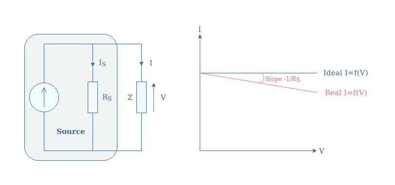
Ideally, a current source provides constant current independent of load resistance or impedance. In practice, the current source has a parallel resistance that is very high, but not infinite. Therefore, the provided current will decrease with the increase of voltage drop on load, due to impedance increase.
Why use current sources?
In many situations, it’s necessary to provide a constant current independent of voltage drop on load. Some application examples:
- Batteries are recharged with current sources.
- For resistive heating systems to keep a constant temperature, the current also must be constant.
- LEDs that need to keep the brightness use this type of source.
The simplest current source
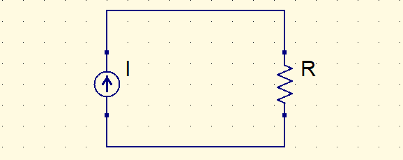
The simplest current source consists of a voltage source in series with a resistor.

This configuration is an economical solution to charge batteries. However, considerable power is wasted by the series resistor. In addition to this, the current changes when load impedance changes.
Designing some current sources
Current source with voltage regulator
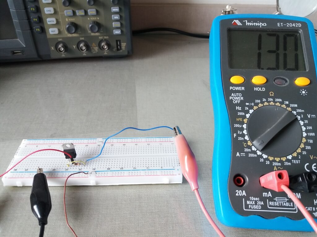
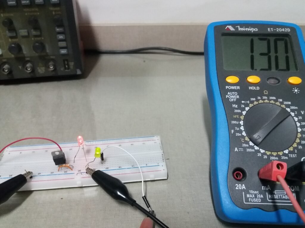
The voltage regulator LM317T can be used as a constant current source.
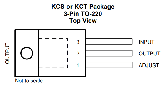
Warning: to this circuit to work, you must use LM317T, not LM317. Otherwise, the output current will change if voltage input Vin changes.

The equation to calculate current output I_{o}.
I_{o}=\frac{1.25}{R}
The R value that I choose was 1 kΩ. Therefore, I_{o} must be 1.25 mA.

Current mirror
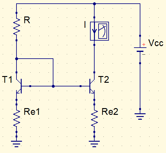
In this circuit, the current that passes through R resistor has the same value as current I through T2’s collector. In this post, are shown current mirrors which use BJT transistors, this component’s operation is in the following link.
How BJT transistor works?Click here
To avoid burning transistors it’s necessary to put a resistor between ground and emitter terminal in each transistor.
- Both Re1 and Re2 are 68 Ω.
- The value Vcc from the source is 12 V.
- T1 and T2 are TIP122. Because lower power transistors will heat up too much, could burn.
- I current must be 30 mA.
Calculating R using Kirchhoff’s voltage sum law. The base-emitter voltage Vbe is 0.7 V.
R+Re=\frac{Vcc-Vbe}{Io}
R+68=\frac{12-0.7}{30m}
R=308\Omega
Was used the commercial value 330 Ω.
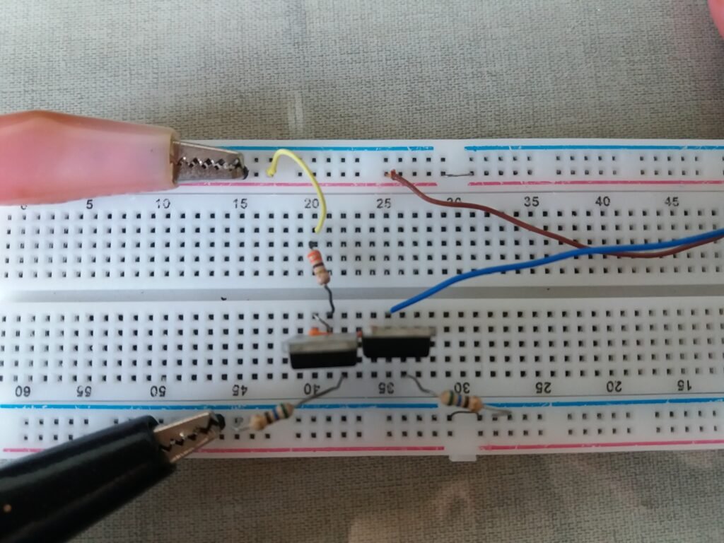
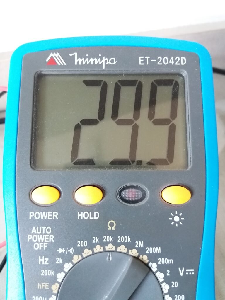
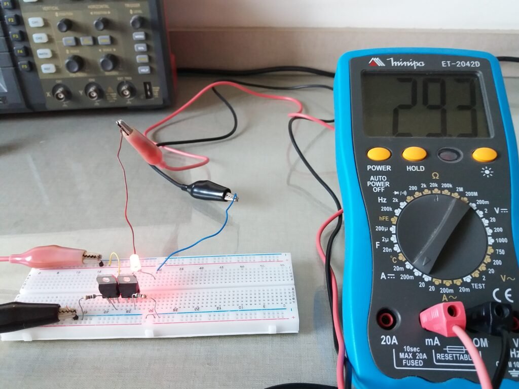
Adding more load, value is approximately the same.

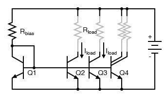
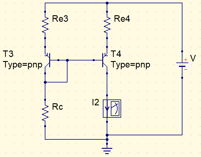
Designing a current mirror with pnp. This time the used model is TIP127.
- The supply voltage is 10 V.
- Resistors on emitter terminals have 150 Ω.
- For Rc, I choose the commercial value 470 Ω.
Calculating I2 current.
V=I2\cdot Re1+Vbe+I2\cdot Rc
10=I2\cdot 150+0,7+I2\cdot 470
I2=15mA
