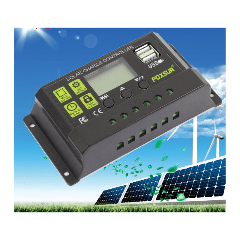
I received a doubt about the charge controller for solar power generation. This component is very important for off-grid systems.
Functions of charge controller
Battery protection
The charge controller protects the batteries from overcharging and sudden discharge. This component monitors voltage value on batteries’ terminal, or battery bank. To avoid overcharging, the controller disconnects the system’s photovoltaic panels when the battery reaches voltage superior limit, which depends on battery. If battery bank’s voltage reaches a inferior limit, determined by battery model, the output for charges is disconnected. These protections greatly increase battery’s lifespan.

Why can’t you link the inverter on controller’s load terminal? Loads (home appliances, devices, etc.) supplied by alternate current can require more power than the controller can handle, which can cause burn. The load output serves for LED lamps and other smaller loads that use direct current on 12 or 24 V. The inverter also has a protection system against battery’s excessive discharge, also called battery low voltage protection.
Battery charge management
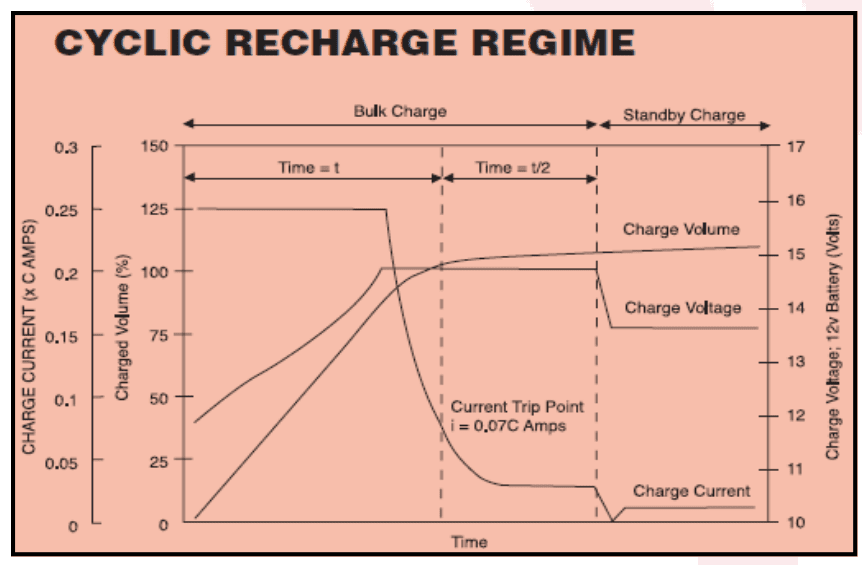
Some controllers have an algorithm to manage charging considering battery charge profile, for optimize charging and increase durability.
Protection against overheating
The controller’s internal temperature is measured by a sensor. In case that temperature reaches a determined limit, the controller’s nominal current is gradually reduced, or the controller disconnect panels’ input and load output until the temperature falls to an acceptable level.
Other protections
The controller can interrupt the current flux for batteries and loads in case of overvoltage, to avoid damage. Some controllers have a pressure sensor, to detect possible gas leak. The load output is immediately shut down when there’s a short circuit.
Charge controller ON/OFF
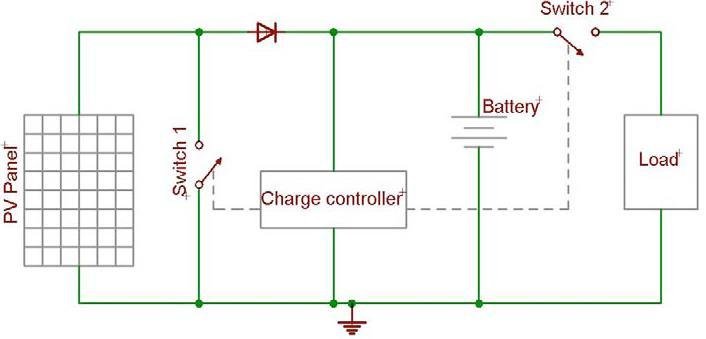
This is the simplest and cheapest, but it’s the least efficient. This type has two switches, that are MOSFET transistors or relays, which allow or interrupt current flux. Exist two configurations of this controller type.
Series configuration
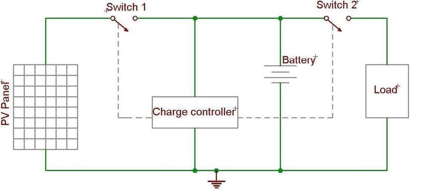
There is a switch 1 linking photovoltaic panels and battery bank. This switch opens when batteries are fully charged and closes when battery’s voltage is below maximum voltage. The switch 2 opens when batteries’ voltage reaches a minimum level.
Shunt configuration
In this configuration, switch 1 is in parallel with photovoltaic modules. To avoid battery overcharge, this switch closes, creating a short-circuit. This short-circuit current is limited module’s maximum current and by solar radiation, therefore, it won’t damage the panels.
PWM charge controller
In case you don’t know what PWM (Pulse Width Modulation) is, click on the following link before continuing.
The keys are controlled by PWM pulses, these are generated by electronic circuits controlled by a microcontroller. The voltage on battery is measured, information is transmitted to microcontroller, which through an algorithm, send pulses considering battery’s charge profile of three stages.
MPPT charge controller
This is the most efficient, however the most expensive. MPPT is the abbreviation of Maximum Power Point Tracking. An algorithm is used to adjust voltage and current on photovoltaic panels output, to obtain maximum power for batteries and loads. Also has switching by PWM.
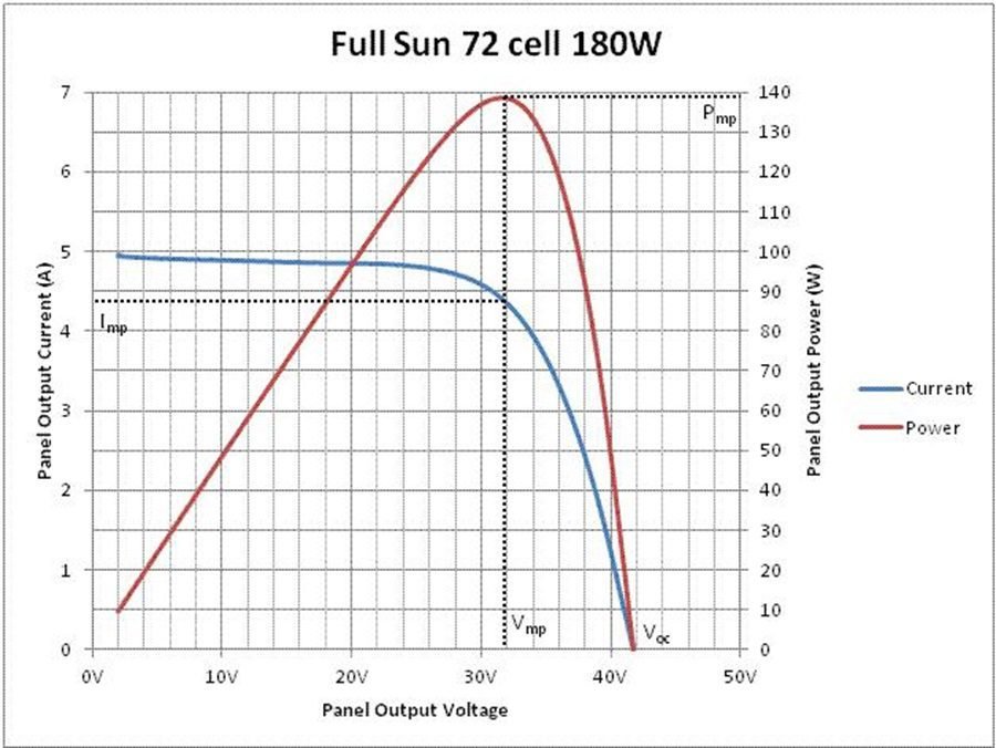
This type of controller has a DC-DC buck converter, which converts high voltage in low, to charge battery. Photovoltaic systems with MPPT controller produce 30% more energy, allowing to use less modules to produce the necessary energy. As shown in the post “How photovoltaic solar panels work? (Part 2)“, the temperature and solar irradiation influence on curve’s size and consequently, on maximum power that can be produced by the panel.

