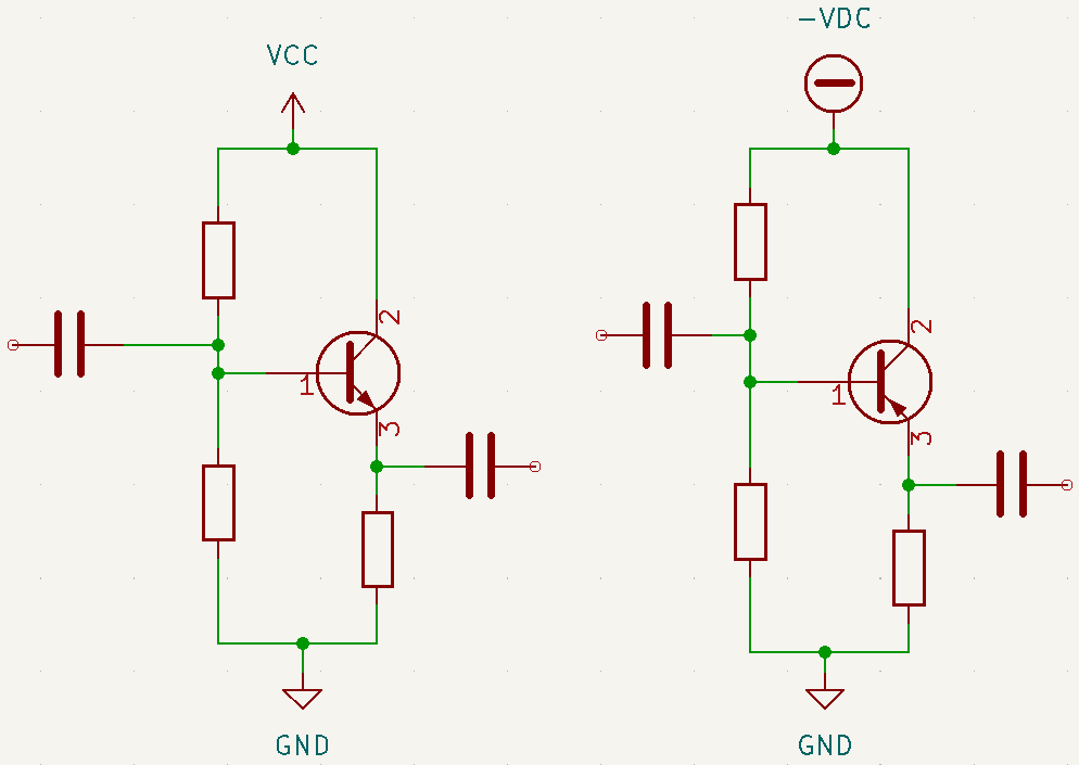
In this post, it is shown another type of amplifier configuration using BJT. This time, it is the common collector or emitter follower.
To know about the BJT transistor’s operation, click on this link.
Common collector amplifier with NPN transistor

The chosen transistor was the 2N3904, whose datasheet is on this link.
Calculating resistors linked to transistor’s base
First, you must determine the voltage on transistor’s base. This value must be lower than supply voltage (Vcc) and higher than base-emitter voltage (V_{BE}).

The formula to obtain voltage base (V_{b}).
V_{b}=V_{BE}+\frac{(V_{cc}-V_{be})}{2}
V_{cc} value was chosen arbitrarily as 8V.V_{b}=0.65+\frac{(8-0.65)}{2}=4.325V
Using the voltage division equation.
V_{b}=\frac{R_{b2}}{R_{b2}+R_{b1}}\cdot V_{cc}
4.325=\frac{R_{b2}}{R_{b2}+R_{b1}}\cdot 8
0.5406=\frac{R_{b2}}{R_{b1}+R_{b2}}
R_{b1}=0.8498\cdot R_{b2}
The closest commercial values of R_{b1} and R_{b2} that meet this proportion are 1kΩ and 1.2kΩ, respectively.
Calculating resistance on emitter
Calculating emitter voltage.
V_{BE}=V_{b}-V_{e}
0.65=4.325-V_{e}
V_{e}=3.675V
To design the resistor Re, it’s necessary define the emitter current (I_{e}). The arbitrarily defined value is 10mA, because it’s a safe value to prevent transistor overheating.
V_{e}=R_{e}\cdot I_{e}
R_{e}=367.5\Omega
The closest available commercial value is 470Ω, which produces an emitter current of 7.81mA.
Designing capacitors
The formula to calculate the input capacitor Ci.
Ci=\frac{1}{2\pi f\cdot Ri}
Where Ri is the input resistance saw by Ci capacitor.
Ri=R_{b1}||R_{b2}||\beta r_{e}
In this case, it wasn’t possible to measure β of transistor on multimeter. On “ON CHARACTERISTICS” part of datasheet shown before, the gain range goes from 100 to 300, when collector current (I_{C}) is 10mA. The gain can be considered as 100. Calculating r_{e} and Ri.
r_{e}=\frac{26mV}{I_{E}}=\frac{26m}{7,81m}=3,329\Omega
R_{b1}||R_{b2}=\frac{R_{b1}\cdot R_{b2}}{R_{b1}+R_{b2}}=523\Omega
\beta\cdot r_{e}=332,9
Ri=\frac{523\cdot 332,9}{523+332,9}=203,42\Omega
With cut frequency 20Hz, input capacitance is:
Ci=39,119\cdot 10^{-6}F
The closest commercial value is 47\cdot 10^{-6}F or 47μF. When higher Ci capacitance, lower will be the cut frequency. Below is the equation to calculate capacitance of Co.
Co=\frac{1}{2\pi \cdot f\cdot Ro}
The formula to calculate the output resistance saw by capacitor.
Ro=\frac{R_{b1}||R_{b2}}{\beta}
Ro=5,23\Omega
Co=1521,5\mu F
The closest commercial value is 2200\mu F.

Common collector amplifier with PNP transistor

In this project, it’s used the PNP transistor 2N3906, whose datasheet is on this link.
Calculating the resistors linked to transistor base
Using the same procedure on previous project, considering negative voltages. The chosen supply voltage is -9V. The base-emitter voltage (V_{BE}) is -0.65V.
V_{B}=V_{BE}+\frac{V_{CC}-V_{BE}}{2}
V_{B}=-0.65+\frac{-9+0.65}{2}=-4.825V
V_{B}=\frac{R_{b2}\cdot V_{CC}}{R_{b2}+R_{b1}}
-4.825=\frac{-9\cdot R_{b2}}{R_{b2}+R_{b1}}
1.15R_{b1}=R_{b2}
The commercial values of R_{b1} and R_{b2} are 1kΩ e 1.2kΩ, respectively. Calculating Re resistance, whose emitter current (I_{E}) is 15mA, a value arbitrarily chosen.
V_{BE}=V_{B}-V_{E}
V_{E}=-4,175V
V_{E}=R_{E}\cdot I_{E}
R_{E}=278\Omega
The commercial value is 330Ω, resulting in a I_{E} of -12.6mA. Calculating Ci and Co values.
Ci=\frac{1}{2\pi f\cdot Ri}
I choose the cut frequency f as 5000Hz.
Ri=R_{b1}||R_{b2}||\beta r_{e}
\beta can also be considered as 100.
r_{e}=\frac{26m}{\left| I_{E}\right|}=2,63\Omega
\beta r_{e}=263
R_{b1}//R_{b2}=\frac{1k\cdot 1,2k}{2,2k}=545\Omega
Ri=\frac{545\cdot 263}{545+263}=177,39\Omega
Ci=\frac{1}{2\pi 5000\cdot 177,39}=179,44\cdot 10^{-9} F
Ci commercial value is 100nF. Designing Co.
Co=\frac{1}{2\pi f\cdot Ro}
Ro=\frac{R_{b1}//R_{b2}}{\beta}=5,45\Omega
Co=\frac{1}{2\pi 5000\cdot 5,45}=5,84\cdot 10^{-6}F
The closest commercial value is 10μF.

Common collector amplifiers video
In the video, blue signal is the input and yellow is output. The type of amplifier gain is 1, therefore, output signal isn’t amplified.


