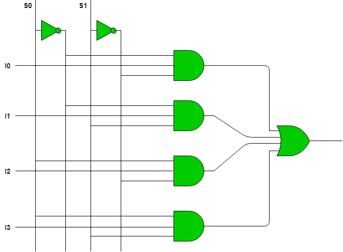
The multiplexer is a combinational circuit with many data inputs and selects one of them to transmit on a single output.
If you don’t know what a combinational circuit is, click on the following link.
Post about combinational circuitsClick here
What is a multiplexer?
The multiplexer (MUX) has many data inputs, a single output, and selection inputs, which determine which input will correspond to the output in a time interval, usually the selection inputs are called address inputs.

Multiplexers usually have 2, 4, 8 or 16 inputs or channels. Therefore, the number of selection inputs must be 1, 2, 3 or 4, respectively. The multiplexer is one of the most important digital circuits in digital electronics and telecommunications, it’s used when need to transmit information from many sources in a single channel.
Multiplexer circuits
2 by 1 multiplexer
This is a project of a multiplexer to work as the digital circuit below.

To implement this circuit like this, it would be necessary three integrated circuits. However, it’s possible to manipulate the logical expression below, to use only NAND gates from a single chip.
Z=I_{o}\cdot\overline{S}+I_{1}\cdot S
Modifying expression using De Morgan theorem.
Z=\overline{\overline{I_{o}\cdot\overline{S}+I_{1}\cdot S}}
Z=\overline{\overline{I_{o}\cdot\overline{S}}\cdot\overline{I_{1}\cdot S}}

Input signals are a squarewave transmitted by an astable 555 and a continuous signal, controlled by a switch, whose value is 5V or 0. A selection switch determines which signal will appear on output. Here’s the complete material list:
- Printed circuit board (PCB).
- Wires.
- 555.
- 74LS00.
- Electrolytic capacitor 100μ x 16V.
- Resistors: 1 of 1.5kΩ, 1 of 560Ω and 3 of 680Ω.
- 2 switches with 1 pole and 3 terminals.
- 3 LEDs.

Circuit with 74LS157
The 74LS157 is a chip with 4 multiplexers 2 by 1, a single selection input and an enable pin, called STROBE. Datasheet is on this link. A switch selection determines the LEDs’ color on output. The complete material list:
- PCB.
- wires.
- 2 switches with 1 pole and 3 terminals.
- 555.
- 74LS157.
- Electrolytic capacitor 100μ x 16V.
- Resistors: 2 of 680Ω, 1 of 1,5kΩ and 1 of 220Ω.
- 2 bicolor LEDs.


Circuit with 74LS151
74LS151 is a multiplexer with 8 inputs. In this circuit, an astable 555 produces a high frequency signal, this signal goes to a 74LS193, which is a 4-bit counter, to divide the signal’s frequency into 4 outputs. I used the 74LS193 in one of my old projects.
Two 74LS193 are in cascade to produce 8 signals in different frequencies, which go the multiplexer’s 8 inputs. 3 push buttons send digital signals “0” or “1” to selection inputs, to determine which signal will appear on output. The electrolytic capacitor serve to reduce noise caused by interference. The complete component list:
- Wires.
- Protoboard.
- 555.
- 2 74LS193 chips.
- 74LS151.
- Ceramic capacitor 47nF.
- Electrolytic capacitor 100μF x 16V.
- Resistors: 1 of 220Ω, 1 of 33kΩ and 3 of 12kΩ.
- 3 push buttons.
Multiplexer circuit’s video
Exists also the inverse of multiplexer, the demultiplexer, which will be subject to another post.


