This post will explain basic electromagnetism concepts. Therefore is destined for beginners in the area.
How photovoltaic solar panels works? (Part 1)
")
This is the first part of topic about photovoltaic panels, which will talk about the working principle and the photovoltaic module structure.

Introduction to MIMO

MIMO means Multiple Input Multiple Output, consist in both the transmitter and receiver have more than one antenna. It is one of the key technologies of 3G and 4G wireless communication.
Servomotors: How do they work?

In this post, I will explain how servomotors work. I will give emphasis on RC servomotor, industrial, and AC. They are very useful in many applications.
Wind turbines: how do they work?
I will give an introduction to how wind turbines work.
Digital Electronics: Combinational circuits

In this post, I will explain how to design combinational circuits, which are just digital circuits with combinations of many logic doors.
Logic gates
We have the following logic doors in IEEE standard.

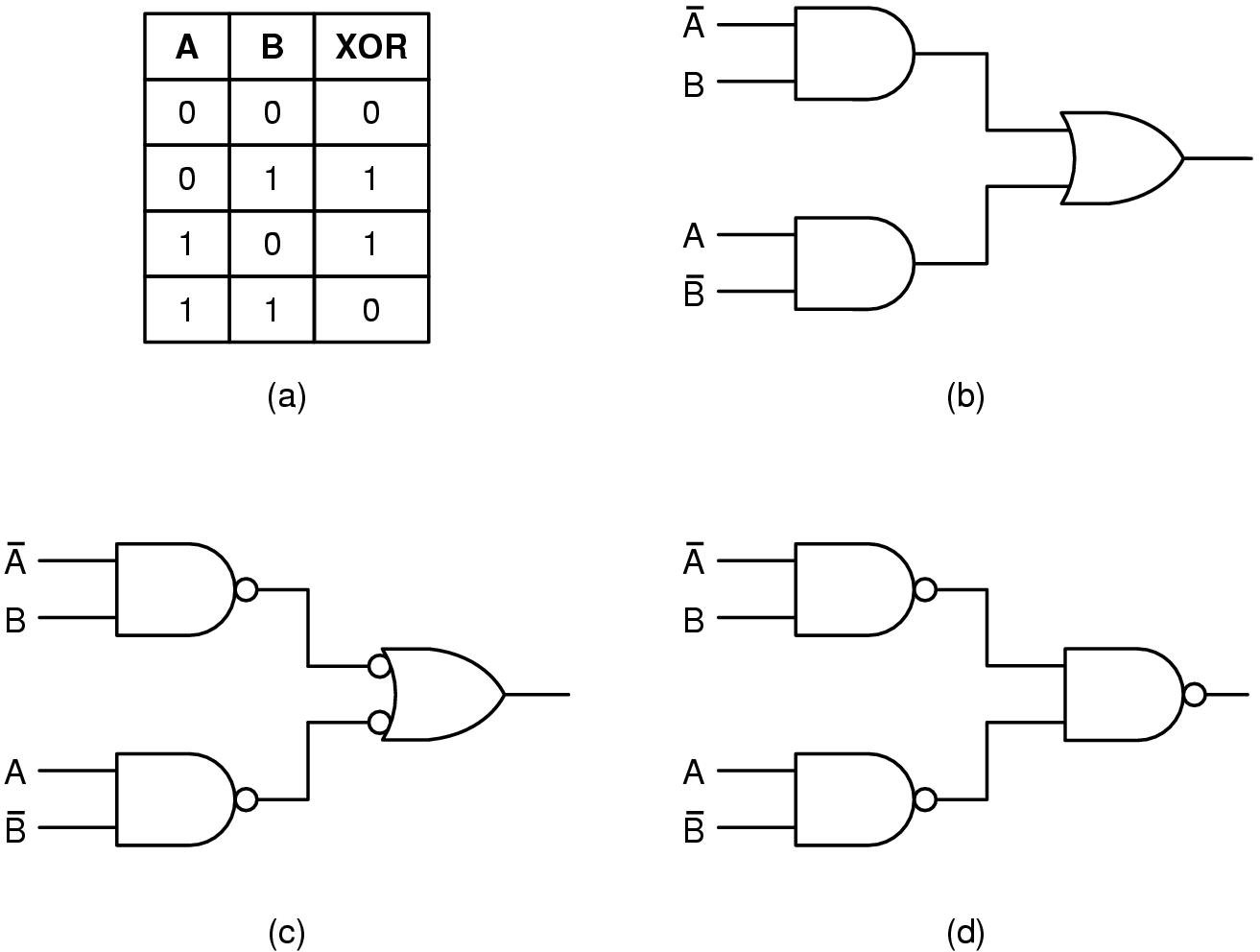
The exclusive OR (XOR) is a combination of logic gates as shown in the figure below and exclusive NOR (XNOR) is XOR with an inverter.
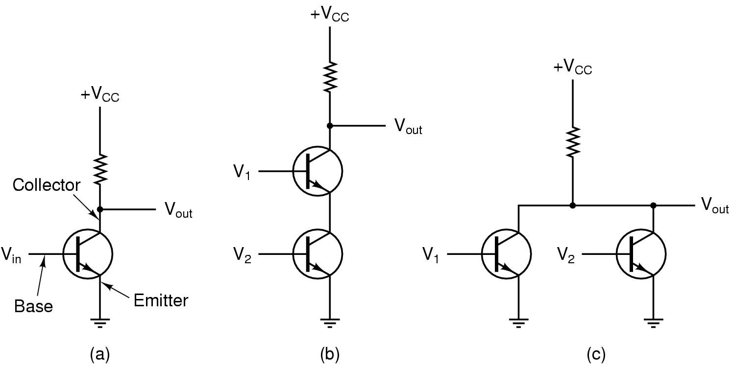
Physically, you can build logic gates with BJT transistors, diodes or CMOS. The CMOS mode is used for integrated circuits.


How to design combinational circuits?
There are the steps to design and build a digital combinational circuit, with an example.
Step 1: Create the truth table.

Step 2: Write in AND to all cases which have “1” output and create an expression in this form.
![]()
Step 3: Simplify the expression, use the Karnaugh map, I will explain in other post.
Step 4: Implement the circuit.

Commercial chips
You can use commercial chips to implement combinational circuits in practice. Here are some few examples.
74LS04


74LS02


74LS00


74LS08


74LS32


Printed circuit board: How to make it?

This is a tutorial about how to make a printed circuit board with the simplest tools in an easy way. I won’t show software here.
Tools needed
- Iron perchloride:

- Piercer board:

- Specific pen to draw in circuit boards (you just need one, I put two for illustration only):

- Tin

- Soldering iron:

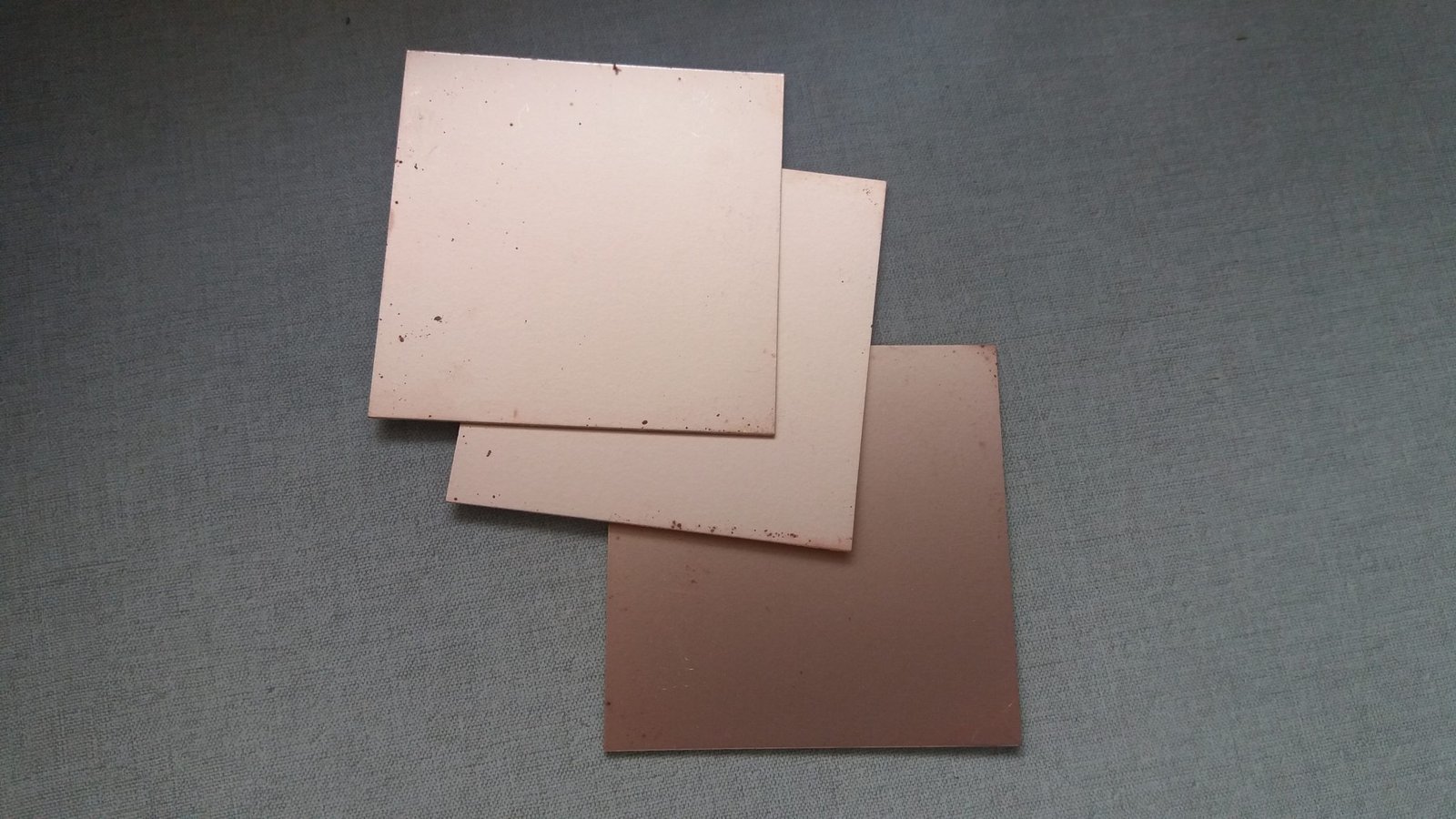
- Phenolite board:
- Board cutter:

- Components at your choice:

Step by step
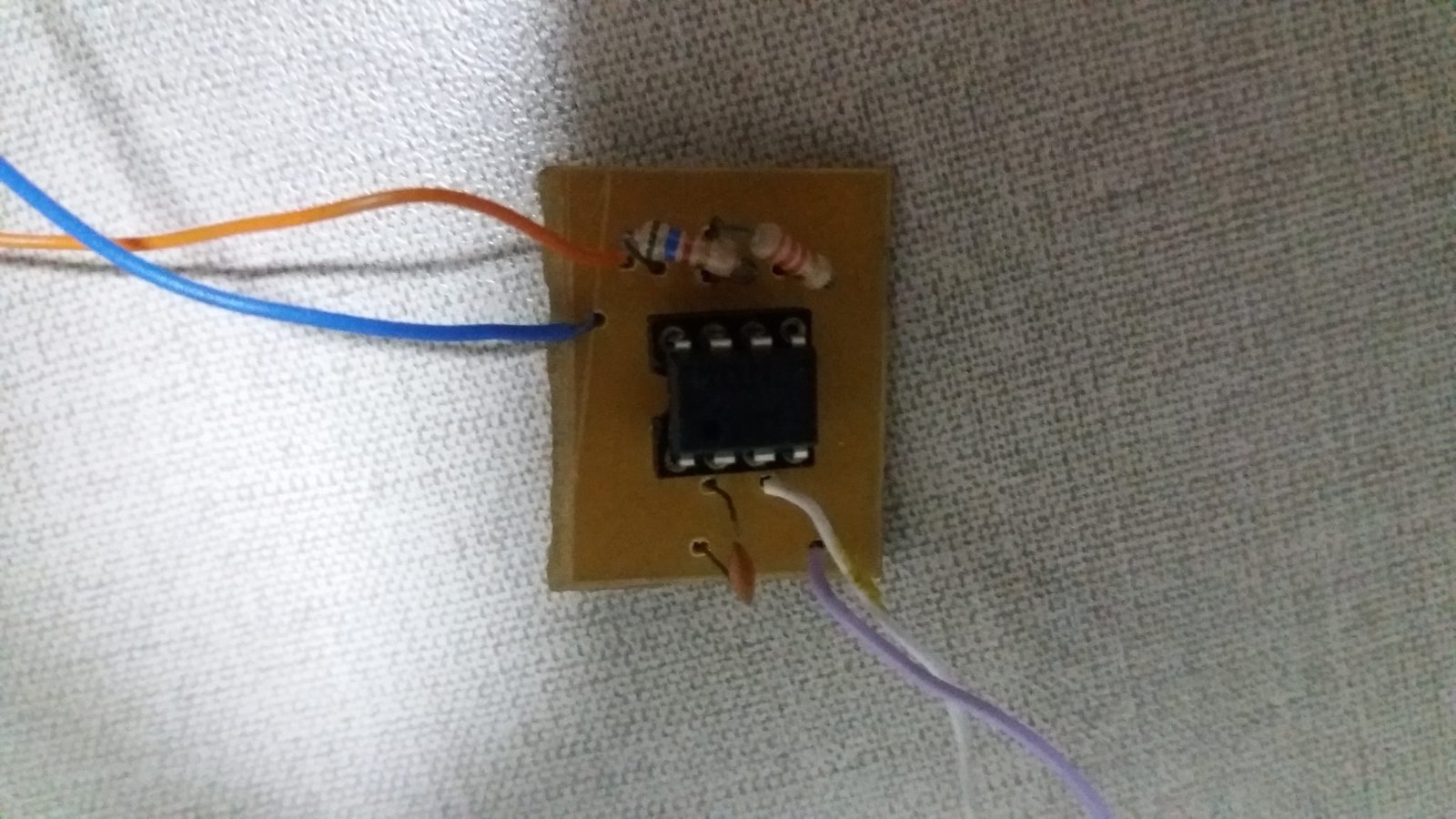
Let’s get an astable 555 as an example, the first thing to do is make the schematics.

Then, cut the phenolite board to a desirable size, to do this, hold the board like in the figure.

Then scratch with the board cutter and turn upside down and do the same again.

After enough scratch, force it to take out the desirable part.

Components will stay on the opposite side of the trails, so draw the trails properly considering this. You should draw the remaining areas and connect it with the ground, to make it more resistant to EM interference and to erode faster in the iron perchloride, but you must make a space between the ground and non-ground trail.

Put the iron perchloride in a plastic recipient.

Put the board with the trails face in the iron perchloride and wait for a while.
After the corrosion is complete, make holes in the board according to the schematics.

You printed circuit board should be like this:

With soldering iron and tin, sold the components.

The circuit is ready. Now is the test, if you have an oscilloscope, you will be able to see a square waveform in the output.