
This post shows how to control a 4 LED arrays module with Arduino and the operation of MAX7219, a Maxim chip.
4 LED arrays module
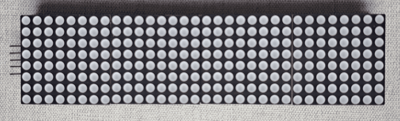
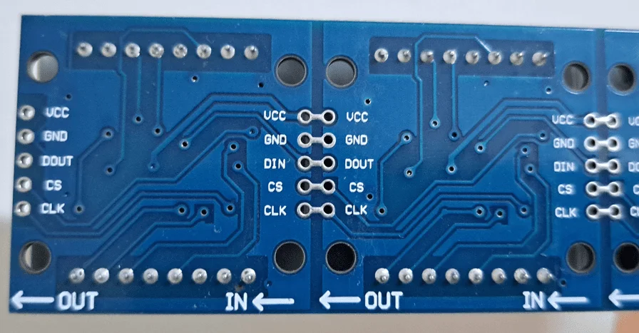
This module has 4 8×8 LED displays arranged in series, and each one has a MAX7219 chip.
MAX7219 operation
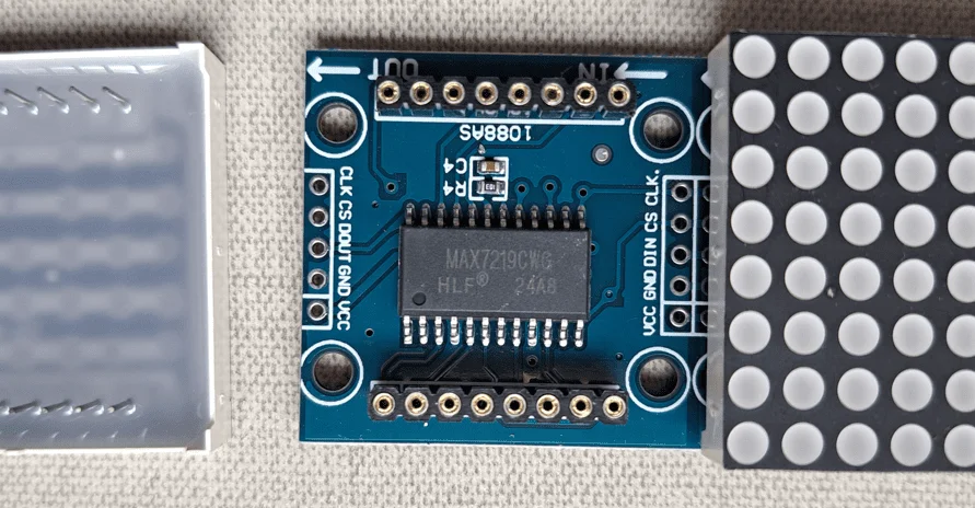
MAX7219 communicates with the microcontroller through SPI interface. CLK is the clock signal, a needed square wave for synchronization and operation of any integrated digital circuit, DIN is the 16-bit input data, from D15 to D0. While CS or LOAD controls data transfer, when CS is on low level or “0”, the 16 bits go to shift register, after the last bit, CS emits a pulse.
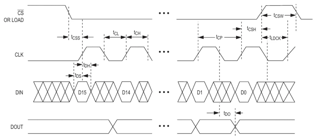
The 16 bits go to a shift register, starting from Most Significative Bit (MSB) to Least Significative Bit (LSB). The first 4 bits aren’t used (D15 to D12), following 4 bits (D11 to D8) have the address, and the 8 following bits represent data.
Registers and multiplexing
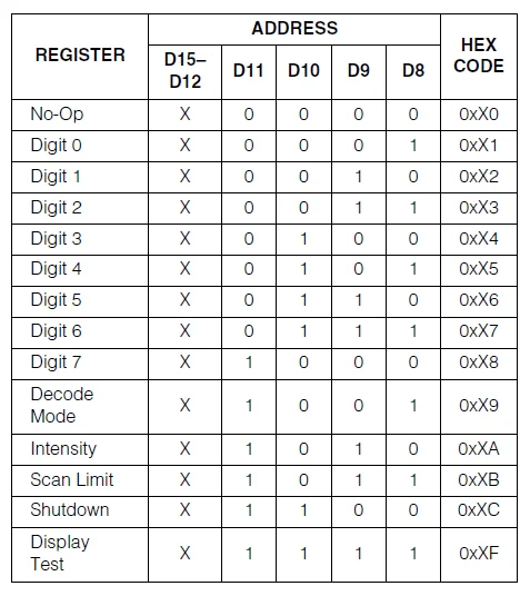
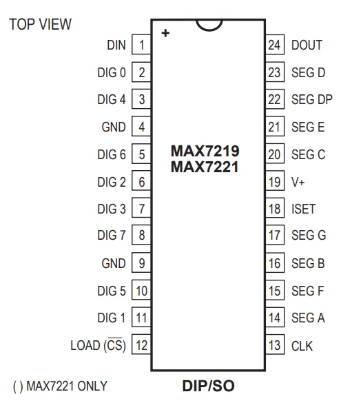
Data is stored in RAM. Each register’s function is:
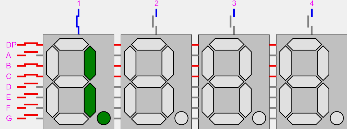
- Digit 0 to 7: In a 64 LED array, each one controls a display line, while in an 8 7-segment display set, it controls each digit.
- Decode Mode: activates the BCD code-B decoder, with the purpose of controlling 7-segment displays.
- Intensity: controls LED brightness through PWM.
- Scan limit: determines how many lines or digits are shown.
- Shutdown: turns off the display.
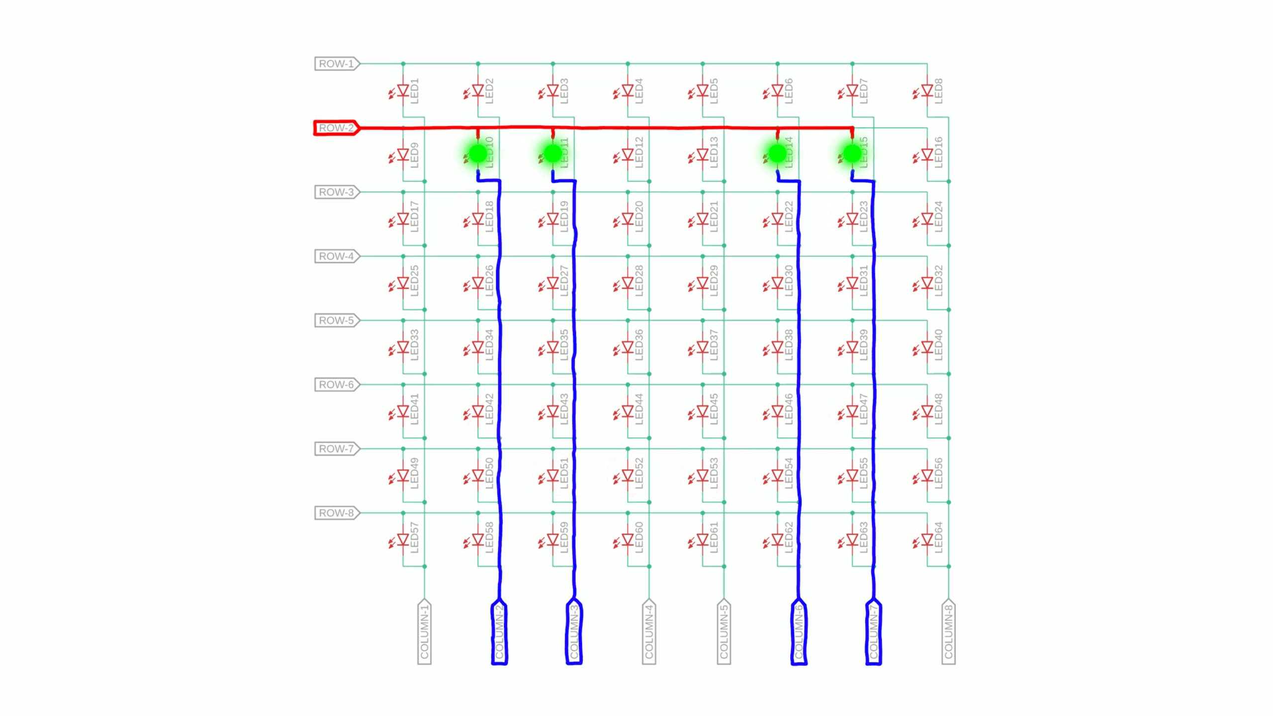
It also has multiplexer circuits, which allow control of 64 LEDs with only 16 terminals.
With this module, it’s possible to create signs, clocks and show any information.
Using with Arduino
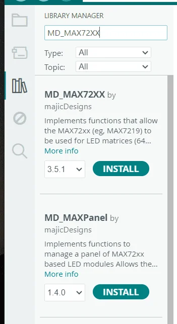
First, it’s necessary to download the library MD_MAX72XX, click on the icon marked with a red circle.
After writing “MD_MAX72XX”, you must install the first library that appears.
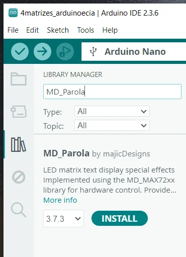
With the finality to greatly facilitate printing phrases on display, go to “Library Manager” on Arduino IDE and in the search bar, write MD_Parola. Then, install the library with this name.
The following code.
#include <MD_Parola.h> //Libraries that must be included.
#include <MD_MAX72xx.h>
#include <SPI.h>
#define HARDWARE_TYPE MD_MAX72XX::FC16_HW //Defines the module as FC-16, which is //the standard 8x32 display module.
#define MAX_DEVICES 4 //Defines the number of LED, which is 4.
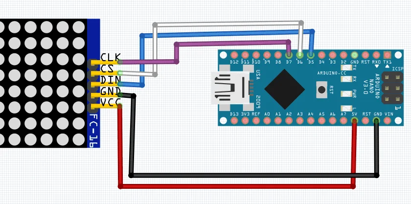
#define DATA_PIN 5 //Define three conection from module to Arduino.
#define CS_PIN 6
#define CLK_PIN 7
//Creates an instance for display.
MD_Parola display=MD_Parola(HARDWARE_TYPE, DATA_PIN, CLK_PIN, CS_PIN, MAX_DEVICES);
void setup() {
display.begin();//Initiates display.
display.setIntensity(4);//Determines LEDs' brightness (from 0 to 15).
display.displayClear();//Clear display.
/*The following line commands what must be printed, the first parameter after "" is the text alignment. Without it, display moves too fast.
The number on second parameter indicates sign exhibition speed, when lower the number, faster.
The third number indicates the pause time after the message passes on display.
The two last parameters are exhibiton effect. It's recommended that both are PA_SCROLL_LEFT or PA_SCROLL_RIGHT.*/
display.displayText("Access Electrical e-Library!",PA_CENTER, 40, 0, PA_SCROLL_LEFT, PA_SCROLL_LEFT);
}
void loop() {
if(display.displayAnimate()){ //Loop which allows display animation.
display.displayReset();
}
}A short video demonstrating the operation.
