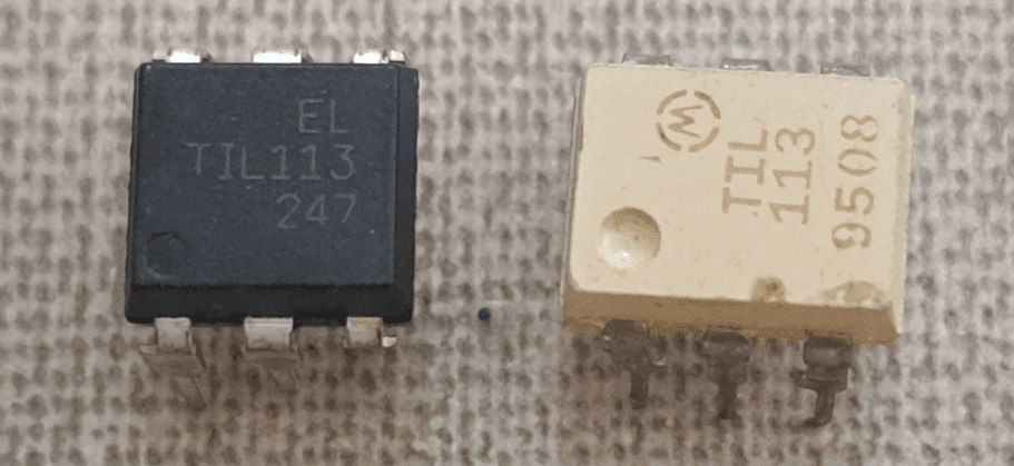
The optocoupler electrically insulates a circuit’s input and output. The operation and some projects are shown in this post.
How it works?
The optocoupler is an integrated circuit with an LED, usually made of gallium arsenide, which emits infrared light. On the opposite side, there is a phototransistor.

Phototransistor operation
It’s a transistor whose current flux is controlled by light. When light hits the semiconductor material, usually made of silicon or germanium, electrons receive energy and go to a more energetic state. Electron-hole pairs are created, and holes are empty spaces without electrons. A potential difference between collector and emitter causes the electrons’ movement, producing a current.

Some optocouplers, such as TIL113, have a Darlington pair, to obtain higher current gain and sensitivity.

Also exist optocouplers with TRIAC, an electronic component whose operation will be explained in a future post.
Some circuits with optocouplers
Optocoupler tester
This is a simple circuit, but it can be useful. Serves to test if an optocoupler with a phototransistor is working. The LED emitter needs a resistor to avoid burn. On the majority of optocouplers’ datasheets, it’s recommended a current I_{f} of 10mA, for a direct voltage V_{f} of 1.2V on the LED. Calculating the value of current limiter resistor R_{f}, considering supply voltage (Vcc) as 6V.
R_{f}=\frac{Vcc-V_{f}}{I_{f}}
R_{f}=\frac{6-1,2}{10m}=480\Omega
The commercial value of resistor for the infrared LED is 470Ω. I recommend that the resistor’s value between IC’s pin 5 and power supply, be at least 10kΩ. Materials’ complete list:
- LED of any color.
- Resistors: 2 of 470Ω and 1 of 18kΩ.
- Support with 6 pins for the chip.
- 4 pin push button.
- 4 AA batteries.
- Support for AA batteries.
- Printed circuit board (PCB).


Zero detector
This circuit receives an alternate current signal from a power plug, which passes through a transformer and a diode full bridge rectifier. When the AC passes through zero, the optocoupler emits a short pulse. Calculating the resistor R_{f}, that will be linked to IR LED. Signal’s amplitude value V_{in} is 11.6V, including the voltage drops on diodes.
R_{f}=\frac{V_{in}-V_{f}}{I_{f}}=\frac{11,6-1,2}{10m}=1,04k\Omega
Therefore, R_{f} commercial value is 1kΩ. Complete list of materials:
- A power plug.
- Transformer with 12V on secondary winding.
- 4 1N4007 diodes.
- Optocoupler TIL113.
- Resistors: 1 of 1kΩ and other of 10kΩ.
- PCB.
- Wires.


Higher power load control
The electric insulation between input and output increases safety and allows power signals, such as from microcontroller outputs, to control components that demand high power. In this circuit, an input voltage of approximately 6V controls a big cooler that requires a higher voltage to spin. When you press the button, the cooler turns on.
Material list:
- A 24V cooler.
- IRF840 MOSFET.
- Resistors: 1 of 1kΩ, 1 of 330Ω and 1 of 12kΩ.
- 4N35 optocoupler.
- 4-pin push button.
- 4 AA batteries.
- Support for 4 AA batteries.
- PCB.
- Wires.


