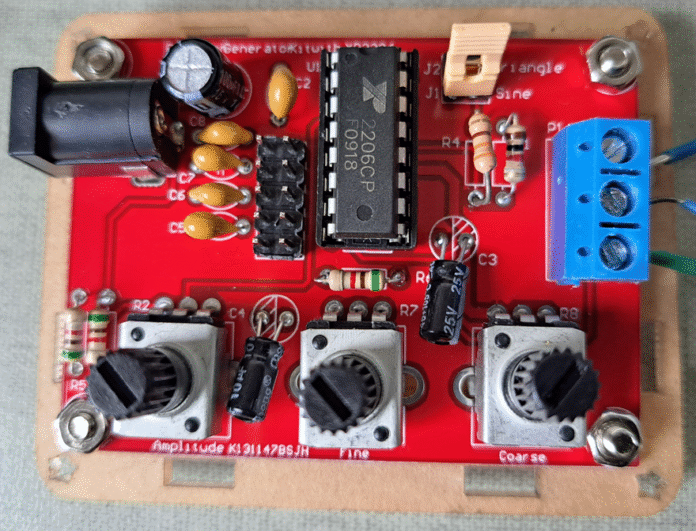
This post shows the assembly process and explains how to use the function generator based on integrated circuit XR2206.
XR2206 function generator specifications
This function generator is a much cheaper alternative than the conventional generators. Although it’s simpler, the XR2206 datasheet can be found on this link. It requires a power supply, which voltage must be between 9V to 12V. It can generate sine, square and triangular waves, with adjustable frequency from 1Hz to 1MHz.
Signal features
Sine:
- Adjustable amplitude between 0 and 3V, with power supply of 9V.
- Distortion lower than 1% at 1kHz.
- Flatness: 0.05dB, between 1Hz and 100kHz.
What is flatness? It’s the signal’s amplitude variation in a frequency range.
Triangular:
- Adjustable amplitude between 0 and 3V, with power supply of 9V.
- Linearity: lower than 1% up to 100kHz.
What is linearity? Its how a system or function output is directly proportional to it’s input.
Square:
- With 9V power supply and without load, amplitude can reach 8V.
- Rise and fall times are 50ns and 30ns, respectively, at 1kHz.
- Symmetry is lower than 5% at 1kHz.
Assembly and use of XR2206 generator
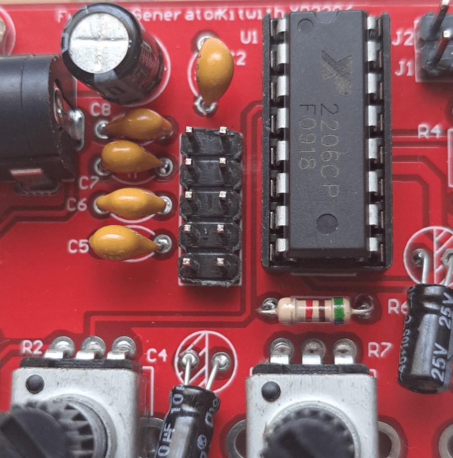
To assemble, just put and solder components on correct positions.

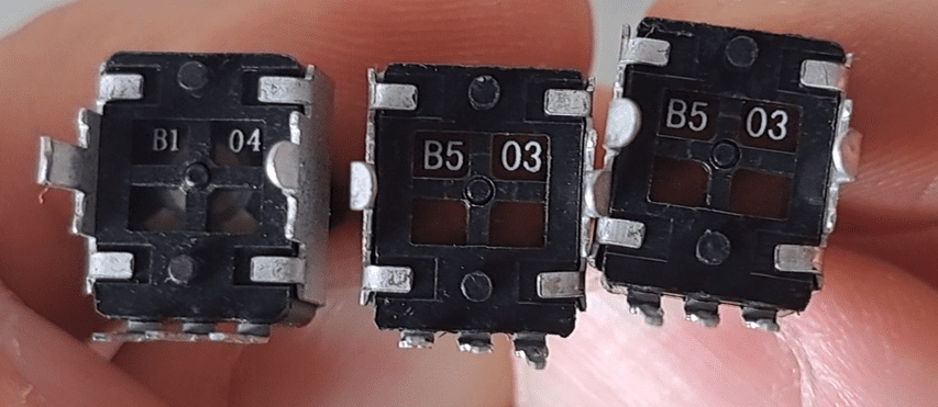
How to use it?
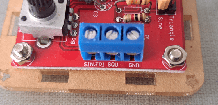


Assembling and demonstration video
In this video, I used a 12V DC power source to supply the kit. Interestingly, when the frequency signal approaches 1MHz, amplitude falls considerably.

