
The transmitter and receiver RF 433 MHz modules are useful for wireless projects with Arduino. In this post, it’s shown how.
I already published a post about how to use these modules, using the integrated circuits HT-12E and HT12D.
Remote control vehicleClick here
RF 433 MHz modules
FS1000A transmitter
Transmits electromagnetic waves on 433 MHz and uses ASK (amplitude shifting keying) modulation.
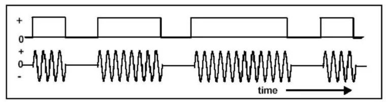
represents a ‘1’ bit. Source: eletrogate.
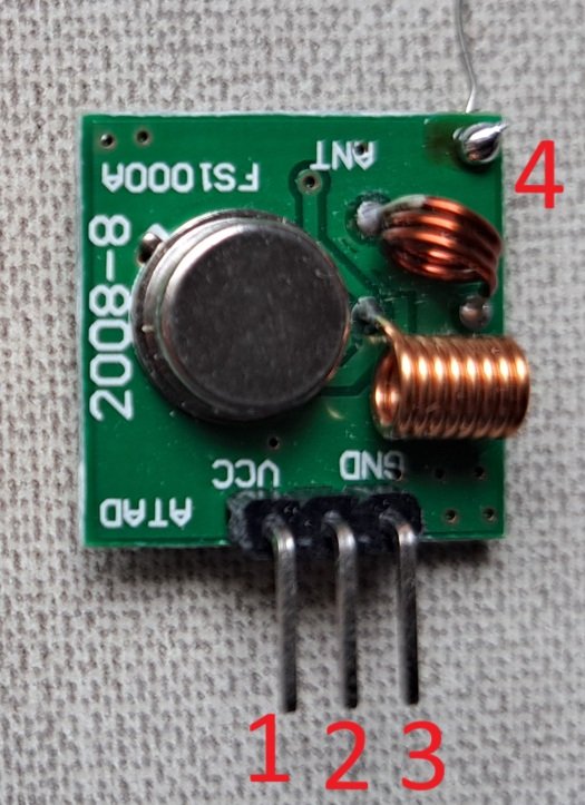
- DATA: data input.
- VCC: supply voltage, can be between 3 and 12 V.
- GND: ground.
- Terminal to install an antenna to increase range. Without an antenna, the range would be only a few meters.
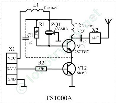
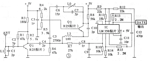
Below is the transmitter circuit, which consists of an oscillator or SAW (Surface Acoustic Wave) resonator, and the VT2 transistor does the switching (turns on and off the oscillator) when it receives signals on its base.
Antenna design
The antenna is just a conductor wire as straight as possible. Since the frequency is 433 MHz:
\lambda =\frac{c}{f}=\frac{3\cdot 10^{8}}{4,33\cdot 10^{8}}=0,69m
Where \lambda is the wave lenght and c is the light speed, which is 3\cdot 10^{8}m/s (meters per second). The type of antenna is a wire whose length D is 1/4 of the wavelength, therefore:
D=\frac{\lambda }{4}=\frac{0,69}{4}=17,28cm
XY-MK-5V receiver
This is more complex; it receives a signal from the transmitter through antenna, and the signal needs to be amplified. Then, it demodulates the signal, which goes to the output pins.
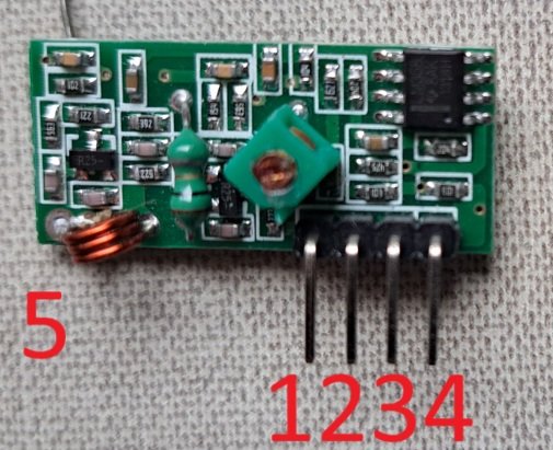
- VCC: supply voltage, which must be only 5V.
- DATA: data output.
- Same as 2.
- GND: ground.
- Terminal to sold antenna.
In addition to the antenna, range also depends on transmitter’s supply voltage. With a good antenna, with no obstacles and no interference, the range can reach up to 300 meters. However, the range falls considerably in an urban or indoor environment. Transmission rate can reach 10 kbps (kilobits per second).
Testing the RF 433 MHz modules
Before testing, it’s necessary to install the Radiohead.h library, whose link is here; I downloaded the most recent version.
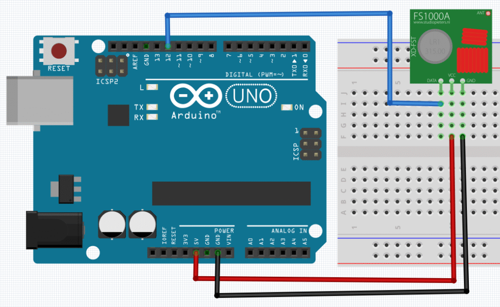
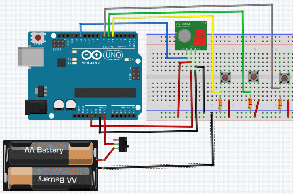
Assemble circuits
Code to test the module.
#include <SPI.h> //SPI library
#include <RH_ASK.h> //ASK library from Radiohead
RH_ASK driver; //An object to control a transmitter module.
void setup() {
Serial.begin(9600);//Initialize Serial screen.
driver.init(); //Initialize communication.
/*if (!driver.init()){ //Alternate form for initializing communication.
Serial.println("init failed");
}*/
}
void loop() {
const char *msg = "Hello receiver!"; //Defines message.
driver.send((uint8_t *)msg, strlen(msg));//Sends message to receiver.
driver.waitPacketSent();//Awaits the sending of information.
delay(400);
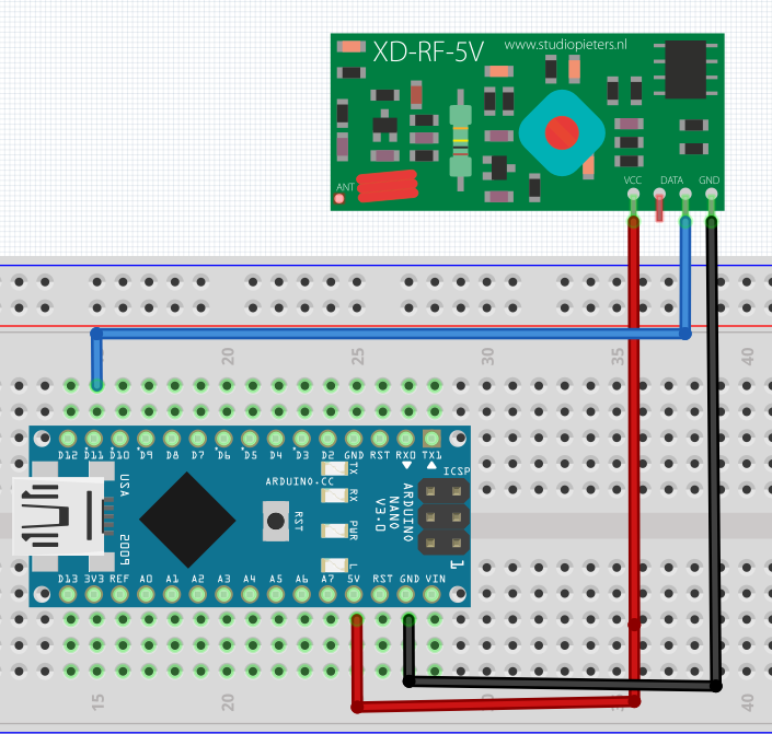
}The schematics and code to test receiver, respectively.
#include <SPI.h> //SPI library
#include <RH_ASK.h> //ASK library from Radiohead
RH_ASK driver; //An object to control a RF module.
void setup() {
Serial.begin(9600);
driver.init(); //Initialize communication.
}
void loop() {
uint8_t buf[RH_ASK_MAX_MESSAGE_LEN];//Receive transmitter message.
uint8_t buflen=sizeof(buf);//Determines the received message's length.
if(driver.recv(buf, &buflen)){//Indicates if received the message.
Serial.print("Message received: ");
Serial.println((char*)buf);
}
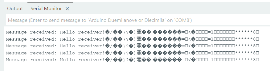
}On the receiver’s Serial screen, must appear the message “Message received: Hello receiver!”
Controlling DC motors
This is a project to control 2 DC motors on the receiver side, sending commands from the transmitter side with 3 buttons.
Component list:
- Wires.
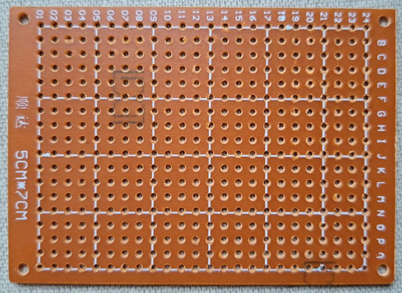
- Circuit board, I used one already with holes.
- Support for 4 AA batteries.
- 4 AA batteries.
- Push button switch with 2 poles or a simple switch with 3 terminals.
- FS1000A.
- Arduino Uno.
- 3 3.3 kΩ resistors.
- 3 push buttons.
The code below.
#include <SPI.h> //SPI library
#include <RH_ASK.h> //ASK library from Radiohead
RH_ASK driver; //An object to control a transmitter module.
const int button1 = 7;
const int button2 = 5;
const int button3 = 6;
void setup() {
Serial.begin(9600);//Initialize the Serial screen.
driver.init(); //Initialize communication.
/*if (!driver.init()){ //Another form to initiate communication.
Serial.println("init failed");
}*/
pinMode(button1,INPUT);
pinMode(button2,INPUT);
pinMode(button3,INPUT);
}
void loop() {
if(digitalRead(button3)==HIGH){
const char *msg = "MOTOR RIGHT FORWARD";//Define message.
driver.send((uint8_t *)msg, strlen(msg));//Sends message to receiver.
driver.waitPacketSent();//Awaits for information to be sent.
Serial.println("MOTOR RIGHT FORWARD");
}else{
const char *msg = "MOTOR RIGHT OFF";
driver.send((uint8_t *)msg, strlen(msg));//Sends message to receiver.
driver.waitPacketSent();//Awaits for information to be sent.
Serial.println("MOTOR RIGHT OFF");
}
if(digitalRead(button2)==HIGH){
const char *msg = "MOTORS BACKWARD";
driver.send((uint8_t *)msg, strlen(msg));//Sends message to receiver.
driver.waitPacketSent();//Awaits for information to be sent.
Serial.println("MOTORS BACKWARD");
}else{
const char *msg = "NO BACKWARD";
driver.send((uint8_t *)msg, strlen(msg));//Sends message to receiver.
driver.waitPacketSent();//Awaits for information to be sent.
Serial.println("NO BACKWARD");
}
if(digitalRead(button1)==HIGH){
const char *msg = "MOTOR LEFT FORWARD";
driver.send((uint8_t *)msg, strlen(msg));//Sends message to receiver.
driver.waitPacketSent();//Awaits for information to be sent.
Serial.println("MOTOR LEFT FORWARD");
}else{
const char *msg = "MOTOR LEFT OFF";
driver.send((uint8_t *)msg, strlen(msg));//Sends message to receiver.
driver.waitPacketSent();//Awaits for information to be sent.
Serial.println("MOTOR LEFT OFF");
}
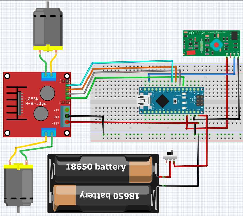
}The complete list of receiver’s components.
- Wires.
- Arduino Nano.
- Small protoboard to put Arduino and connections.
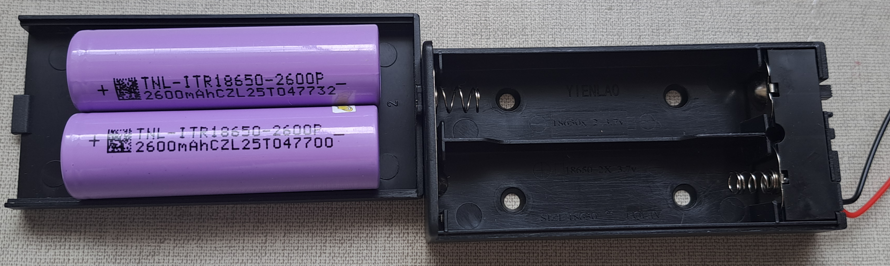
- 2 2600 mAh Li-ion batteries and support for them.
- Simple switch with 3 terminals.
- XY-MK-5V.
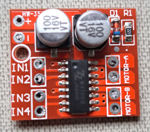
- Mini H-bridge L298N.
- 2 DC motors.
Schematics and code of the receiver, respectively.
#include <SPI.h>
#include <RH_ASK.h>
RH_ASK driver;
int IN1=2;
int IN2=3;
int IN3=4;
int IN4=5;
void setup() {
Serial.begin(9600);
driver.init();
pinMode(IN1,OUTPUT);
pinMode(IN2,OUTPUT);
pinMode(IN3,OUTPUT);
pinMode(IN4,OUTPUT);
}
void loop() {
uint8_t buf[RH_ASK_MAX_MESSAGE_LEN];/*Receives and determines transmitter's
message size.*/
uint8_t buflen=sizeof(buf);//Determines received message length.
if(driver.recv(buf, &buflen)){
buf[buflen]='\0';//Clears the message, removing unecessary characters.
String command=String((char*)buf);//Converts message in string.
driver.printBuffer("Message received: ",buf,buflen);/*buf shows the messa
ge in hexadecimal numbers and buflen shows message's size.*/
Serial.println("\n");
Serial.print("Message received: ");
Serial.println(buflen);
Serial.println((char*)buf);
if(command=="MOTOR LEFT FORWARD"){
digitalWrite(IN1,HIGH);
digitalWrite(IN2,LOW);
}else if (command=="MOTOR LEFT OFF"){
digitalWrite(IN1,LOW);
digitalWrite(IN2,LOW);
}
if(command=="MOTORS BACKWARD"){
digitalWrite(IN1,LOW);
digitalWrite(IN2,HIGH);
digitalWrite(IN3,LOW);
digitalWrite(IN4,HIGH);
}else if (command=="NO BACKWARD"){
digitalWrite(IN1,LOW);
digitalWrite(IN2,LOW);
digitalWrite(IN3,LOW);
digitalWrite(IN4,LOW);
}
if(command=="MOTOR RIGHT FORWARD"){
digitalWrite(IN3,HIGH);
digitalWrite(IN4,LOW);
}else if (command=="MOTOR RIGHT OFF"){
digitalWrite(IN3,LOW);
digitalWrite(IN4,LOW);
}
}
}
The video below shows this project operating, controlling a model ship through RF.
