This is the first part of the series of posts about many types of oscillators, which are very useful circuits.
Oscillators circuits
Oscillators are circuits whose output is a periodic signal with an amplitude that varies with time. Consists in an amplifier and a positive feedback circuit.
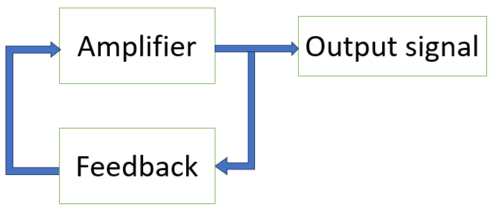
All electronic components produce a thermal noise, or Johnson-Nyquist noise, which is caused by random movement of electrons on conductors and semiconductors, when temperature is over absolute zero. This noise produces small and random values of voltage and current. The feedback circuit filters the noise, to have oscillation in a determined frequency, while the amplifier increases the filtered signal’s amplitude.
Barkhausen criteria
Unity loop gain
They are the criteria a circuit must satisfy to be an oscillator. One of these criteria is the following condition:
\left | \beta \cdot A\right |=1
Where A is the amplifier voltage gain, by that, output voltage divided by amplifier’s input voltage. \beta is output signal attenuation in relation to the input, on feedback circuit. The bars \left | \right | indicate module, by that, the \beta \cdot A value can be positive or negative.
If closed loop gain (\beta \cdot A) is lower than 1, oscillation will lessen until it disappears. If it higher than 1, there will be saturation, consequently, signal distortion.
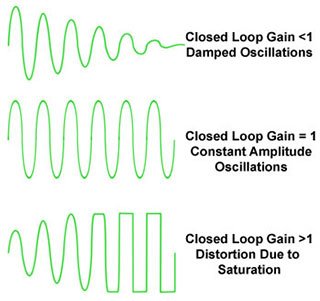
In practice, \beta \cdot A is designed to be slightly than 1, so that the circuit can start oscillation on its own.
360º phase shifting
Both the feedback circuit and the amplifier must have a phase shifting of 180º, so the total phase shifting can be 360º.
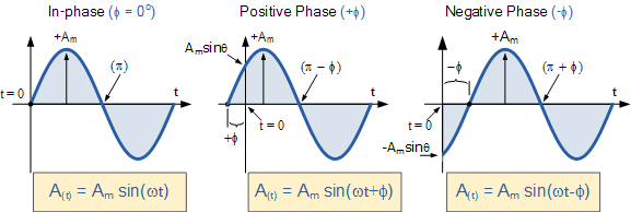
Without this phase shifting, there is no positive feedback.
Types of oscillators
Phase-shift oscillator
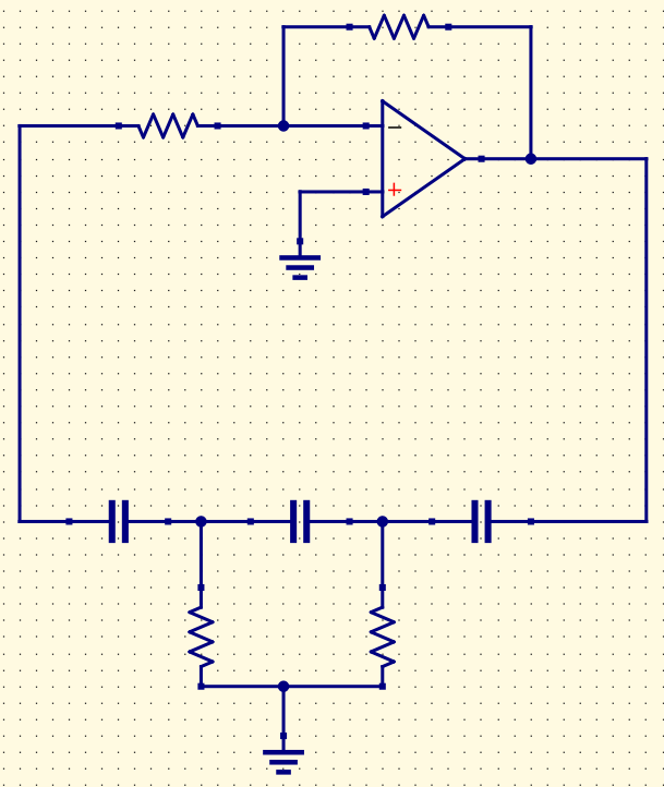
In this circuit, resistors and capacitors on feedback make the 180º phase shifting. Amplifier can have an op-amp, a BJT or a FET. To have a sustainable oscillation at the output, amplifier gain Av must be higher than 29. Below is the formula to calculate oscillation frequency f.
f=\frac{1}{2\pi RC\sqrt{6}}
Where R and C are the values of resistors and capacitors on feedback circuit, respectively.
Phase-shift oscillator project
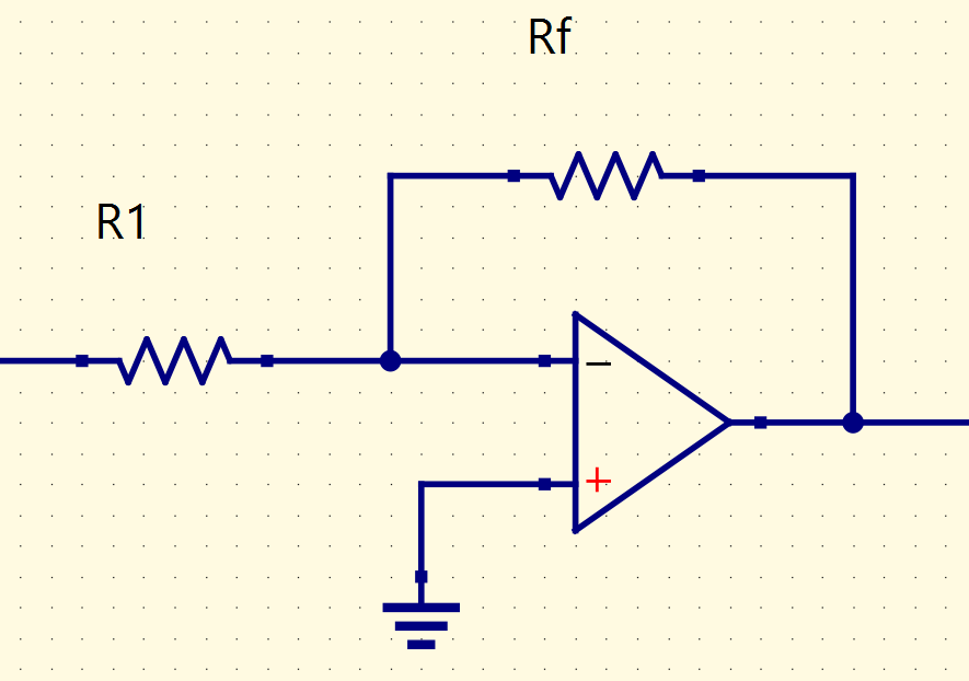
This project has an inverter amplifier with a LM741 op-amp, whose datasheet is here. To have a gain higher than 29, I arbitrarily chose R1 and Rf values as 1kΩ and 33kΩ, respectively.
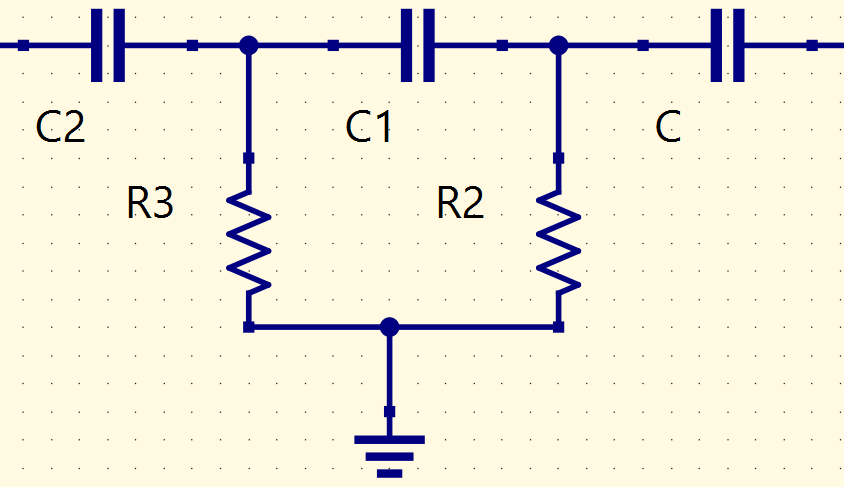
Values of resistors (R2 and R3) and capacitors (C, C1 and C2) from feedback must be equal, I chose the respectively values: 1kΩ and 100nF.
Calculating oscillation frequency with the determined values above:
f=\frac{1}{2\pi RC\sqrt{6}}=\frac{1}{2\pi 10^{3}\cdot 100\cdot 10^{-9}\sqrt{6}}=\frac{1}{15,39\cdot 10^{-4}}=0,0649\cdot 10^{4}=649Hz
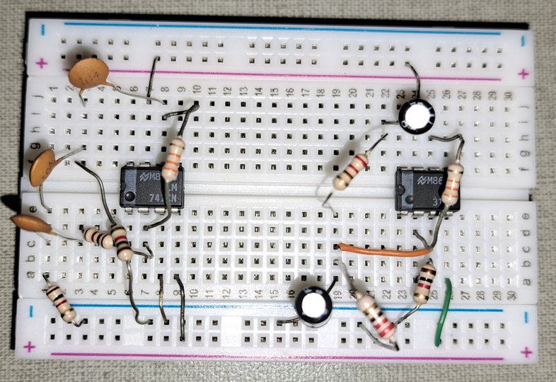
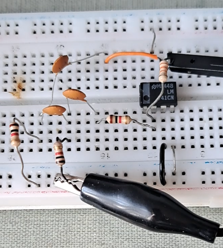
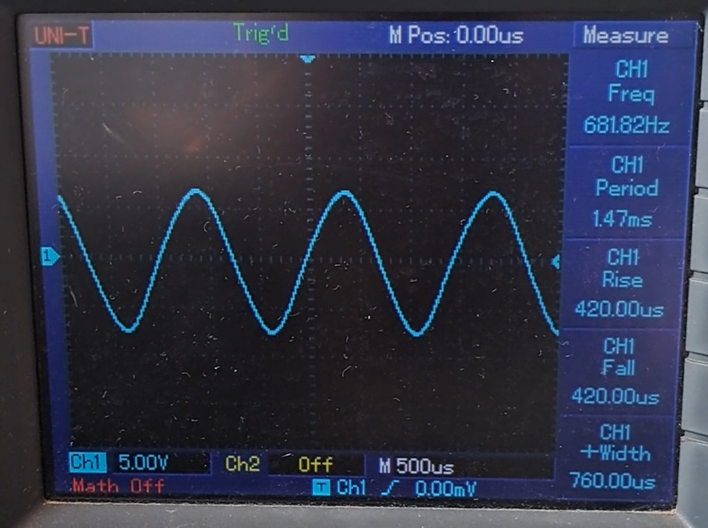
The phase-shift oscillator on a protoboard and its output signal on oscilloscope, respectively.
Wien bridge oscillator
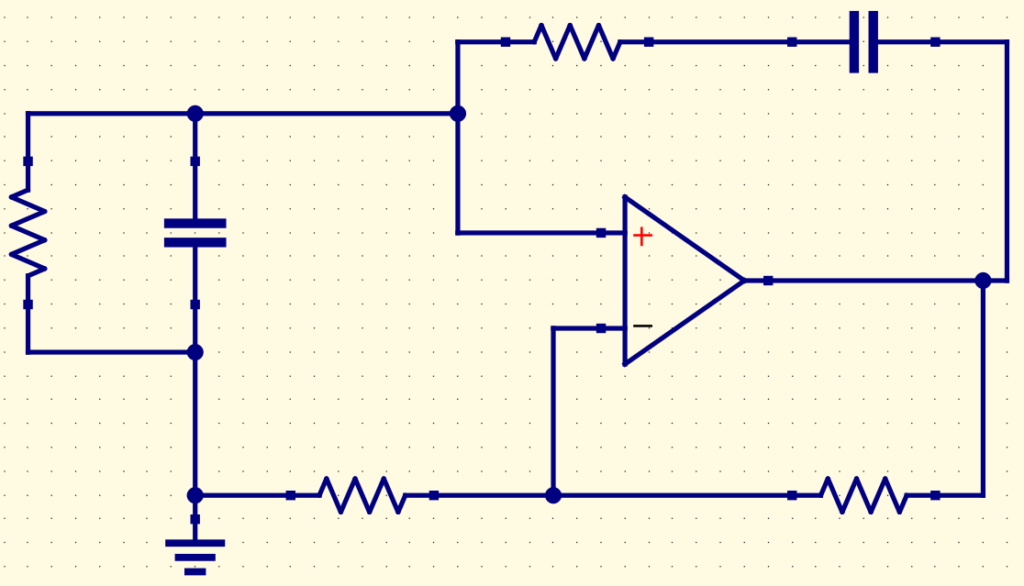
In this circuit, the feedback mesh is a RC bridge. The R1 and R2 resistors, connected to op-amp’s inverter input determine the gain, while the other resistors (R3 and R4) and the capacitors (C1 and C2) define frequency oscillation. The op-amp, R1 and R2 form a non-inverter amplifier. Therefore, to have a stable oscillation, the amplifier’s gain must be at least higher than 3, so the relation R1/R2 must be higher than 2.
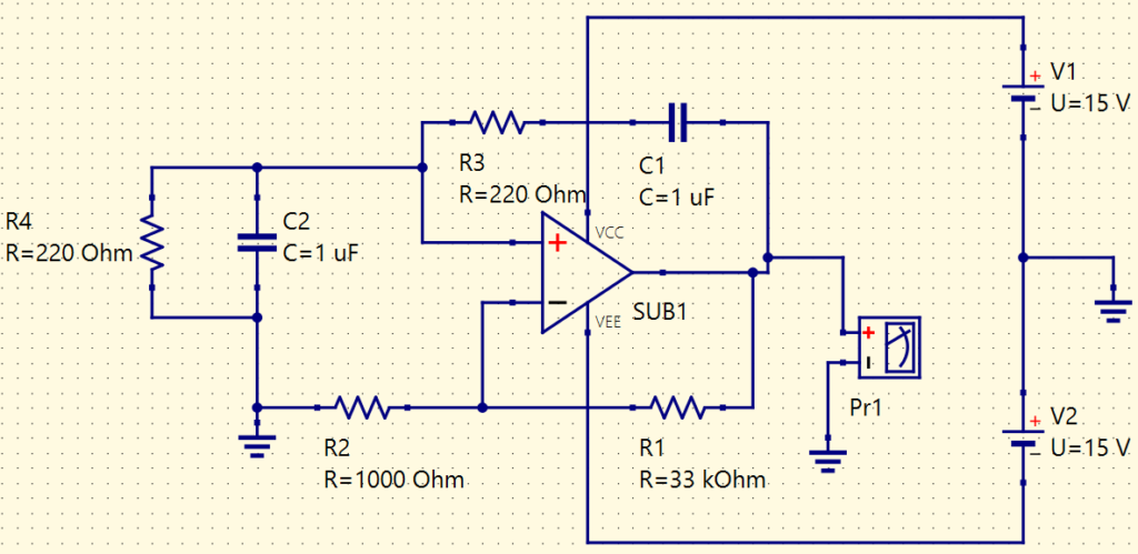
For this project, the gain is 33. The formula to calculate frequency fo:
fo=\frac{1}{2\pi \sqrt{R3\cdot C1\cdot R4\cdot C2}}
Since R3=R4=R and C1=C2=C, the equation becomes:
fo=\frac{1}{2\pi RC}
If R=220Ω and C=1μF:
fo=\frac{1}{2\pi RC}=\frac{1}{2\pi \cdot 220\cdot 10^{-6}}=723,34Hz
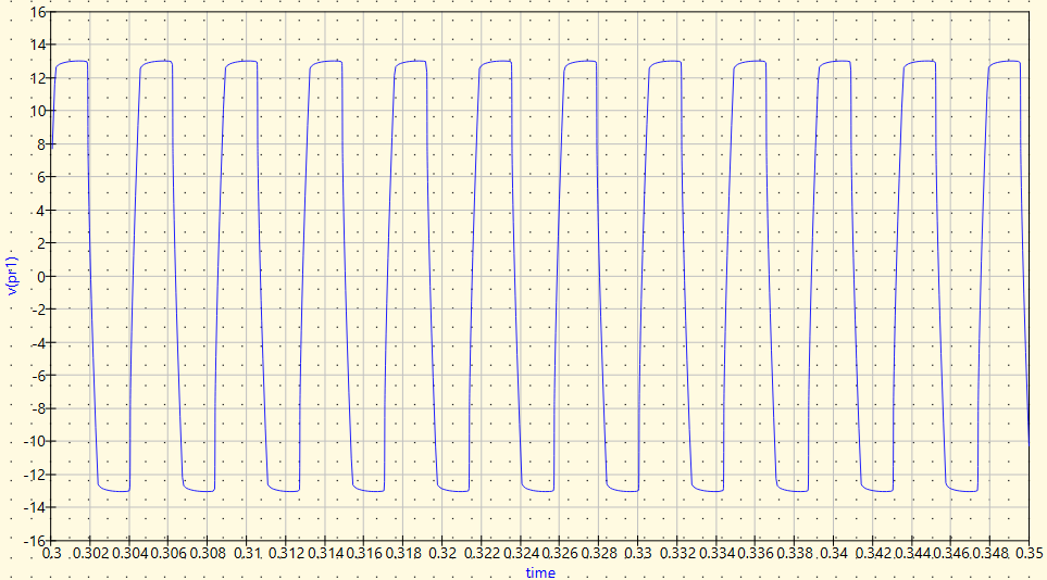
The operacional amplifier is also LM741. Simulating on Qucs-S, this is the output signal.
Improving output signal
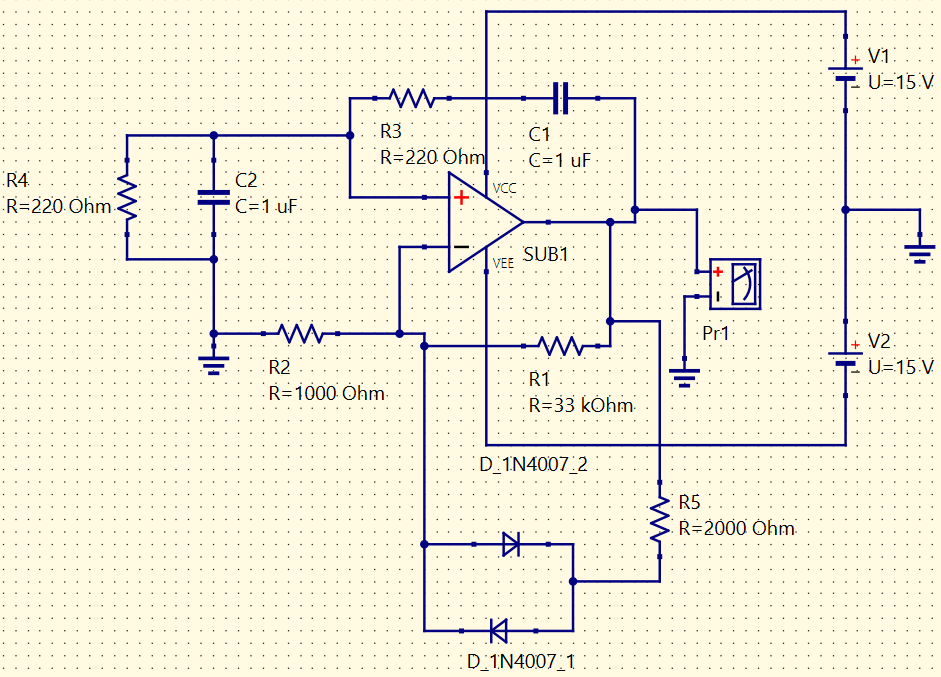
Due to elevated gain, Wien bridge oscillator’s circuit becomes distorted. To make the signal as close to a sine wave as possible, a stabilizer is implemented, consists in diodes in antiparallel, in series with R5 resistor, and this set is positioned in parallel with R1. When one of these diodes is forward biased, it reduces signal’s amplitude.
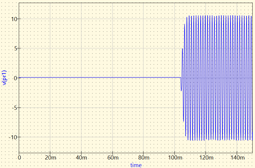
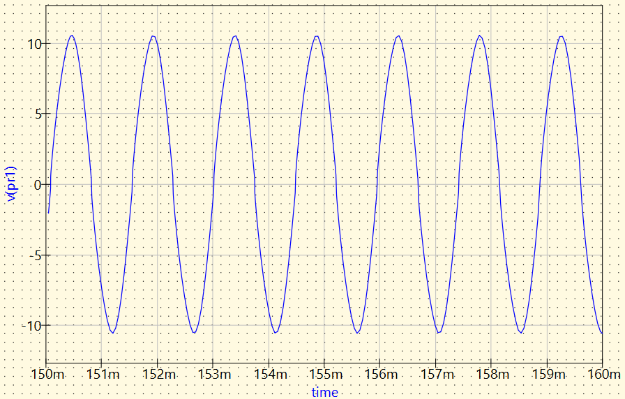
Although the gain is reduced, the signal becomes closer to a sine wave. However, there is a small distortion.
The oscillators’ demonstration video.