Dominate the RC, RL and RLC passive filters, learn how do they work, useful formulas and frequency response. Access!
What are passive filters?
They are circuits that allow signals from a determined frequency range and block signals outside this frequency range, they only have passive components (resistors, capacitor and/or inductors). In alternate current circuits, capacitors and inductors have impedance, which changes when frequency varies. To know more about impedance, click on the following link.
Resistance, Capacitance, Inductance, Impedance and ReactanceClick here
The formulas of capacitive and inductive reactances, respectively:
X_{c}=\frac{1}{2\pi f\cdot C}
X_{l}=2\pi f\cdot L
These formulas show that in a very high frequency, the capacitor behaves like short-circuit, while the coil behaves like an open circuit. For this reason, some input signals in determined frequencies are attenuated by the filters. The cutoff frequency depends on capacitance or inductance of capacitor and coil, respectively. Filters made with resistors and capacitors are called RC filters.
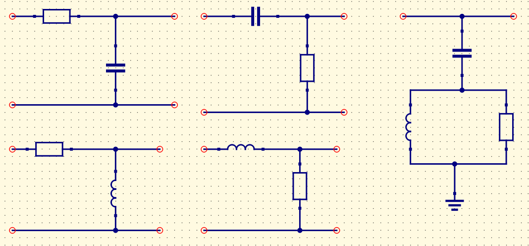
Low-pass RC
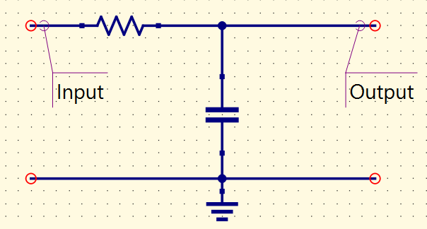
It attenuates electric signals whose frequencies are higher than the cutoff frequency and allows the passage of lower frequencies.
High-pass RC
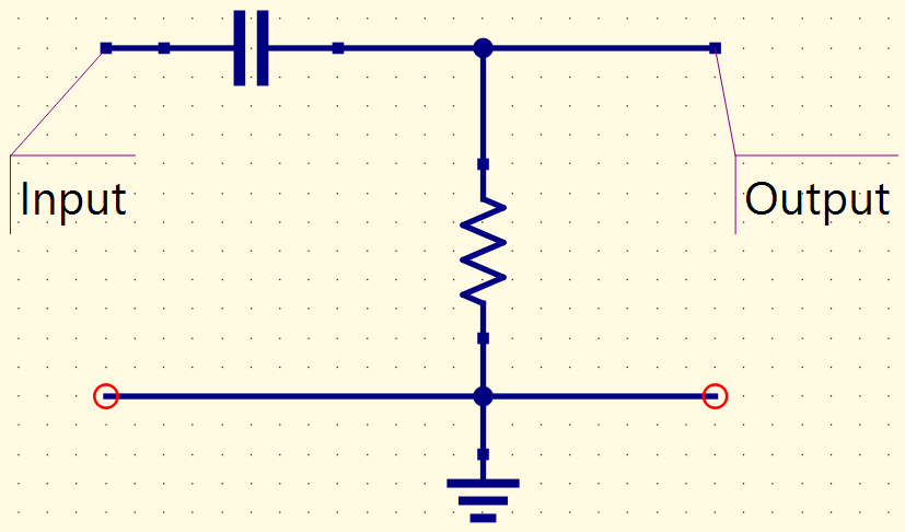
It does the inverse of low-pass filter, allows only the passage of signals whose frequency is higher than cutoff frequency.
Demonstration of cutoff frequency equation for RC filters
First, considers voltage division equation.
- For low-pass filters:
Vo=Vi(\frac{Zc}{Zc+R})
Since Zc=-jXc:
\frac{Vo}{Vi}=\frac{-jXc}{R-jXc}=\frac{Xc\angle-90}{\sqrt{(R^2+Xc^2)}\angle-tg^{-1}(Xc/R)}
On cutoff frequency f, Xc=R. Therefore, real part becomes:
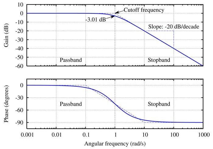
Av=\frac{Vo}{Vi}=\frac{Xc}{\sqrt{R^2+Xc^2}}=\frac{R}{\sqrt{2R^2}}=\frac{1}{\sqrt{2}}=0,707
While the imaginary part:
\theta=-90^{\circ}+tg^{-1}1=-45^{\circ}
Considering Xc=R:
\frac{1}{2\pi f\cdot C}=R
\frac{1}{2\pi R\cdot C}=f
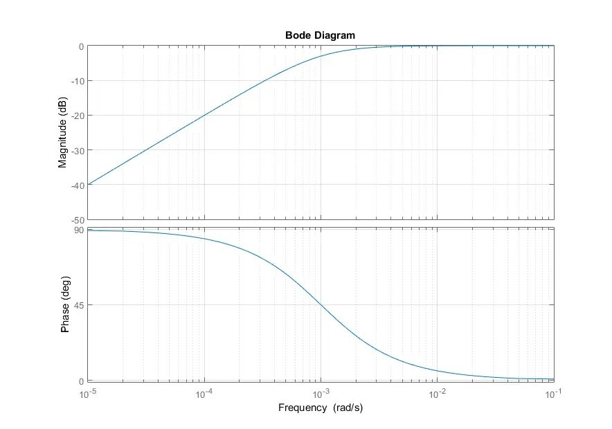
For high-pass RC filters, cutoff frequency formula is the same, but the phase angle \theta is 45º.
Passive filters with coils
It’s perfectly possible to build filters with coils, instead of capacitors, these are the RL filters. However, for low cutoff frequencies, the inductors needs high inductance, making them big and expensive.
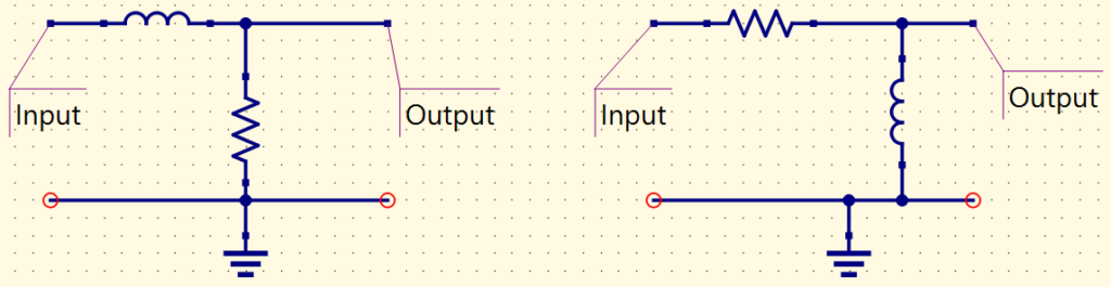
Cutoff frequency and Bode diagram of RL filters
- For low-pass RL filters.
Vo=Vi(\frac{R}{Z_{L}+R})
Considering Z_{L}=jX_{L}:
\frac{Vo}{Vi}=\frac{R}{R+jX_{L}}=\frac{R}{\sqrt{(R^{2}+X_{L}^{2})}\angle tg^{-1}(R/X_{L})}
On cutoff frequency, the gain Av is also 0.707 and phase angle \theta is -45º. While for high-pass RL filters, the phase angle is +45º. The cutoff frequency formula is:
R=2\pi fL
f=\frac{R}{2\pi L}
Pass-band and stop-band
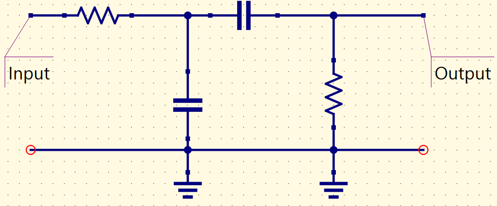
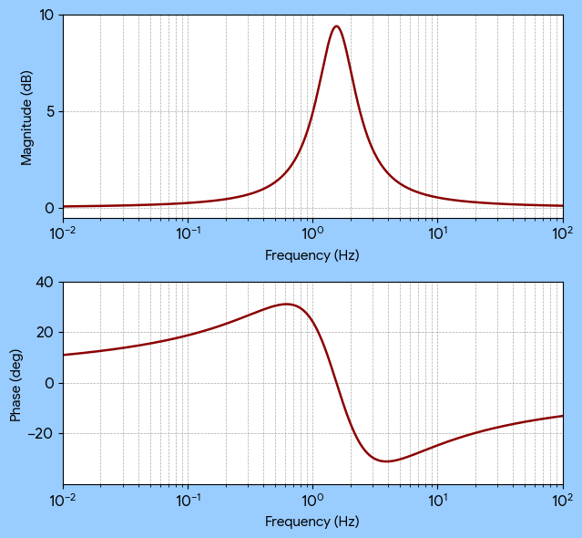
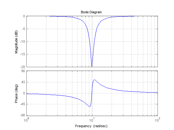
It has two cutoff frequencies: lower and higher, to allow or block a signal from a band determined by the cutoff frequencies. Can be formed by a low-pass and a high-pass is series, a RLC circuit, which uses resistor, capacitor and inductor, or an algorithm who filtrates signals.
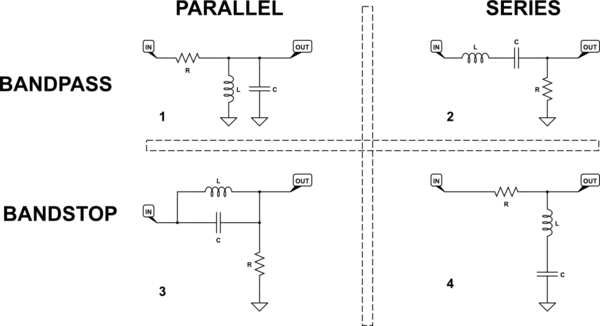
To calculate the lower cutoff frequency (f_{c1}) and the higher cutoff frequency (f_{c2}) of a RLC filter: