
The symmetrical power source for operational amplifiers that I built had a problem. In this post, it’s reported how I corrected it.
Post about symmetrical power sourceClick here
Power sources’ internal resistances
A real voltage source has an internal resistance Rf.
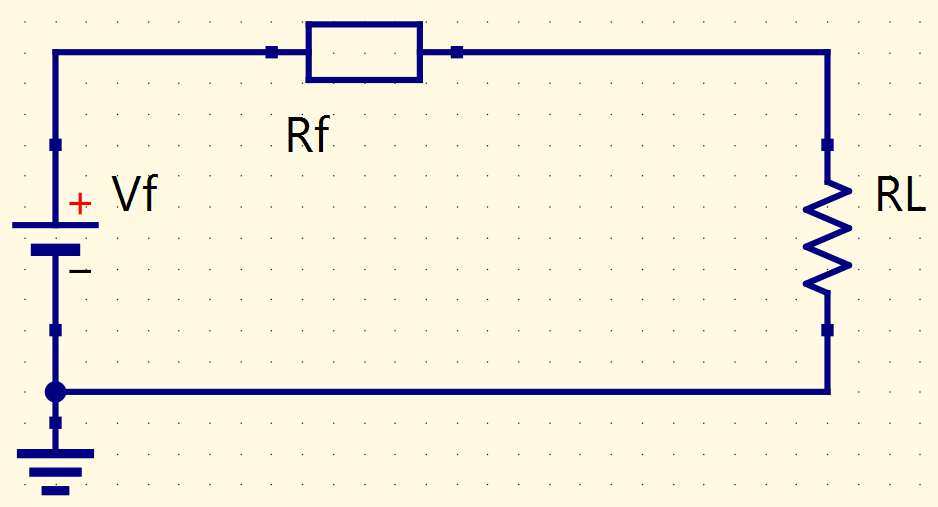
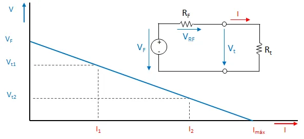
Because of that, source’s voltage falls when it supplies a circuit. If the circuit requires more current, the provided voltage will be lower.
Calculating internal resistance of the symmetrical power source’s first version
Between R1 and R2, whose values are 33kΩ and 15kΩ, respectively, the measured value was 16V. When you connect this point to a 10kΩ, the voltage on source’s terminals drops to 6.5V.
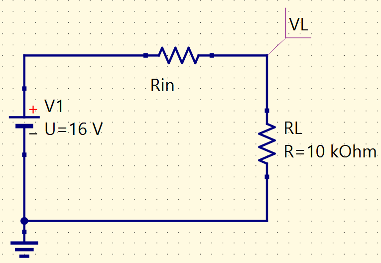
Calculating internal resistance Rin.
Now, calculating internal resistance, when the nominal voltage is 6.2V. There is a drop to 3.4V when it’s connected to a 10kΩ resistor.
Solving the problem
Internal resistance must be as close as possible to zero. The resistors were replaced by voltage regulators.
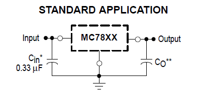
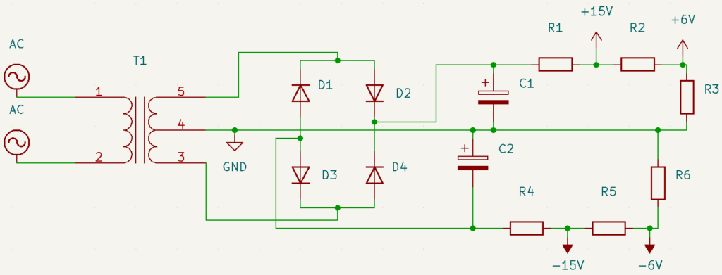
Voltage regulators need capacitors on input and output, for noise reduction and protection against interference and voltage input oscillations. Below is the power source’s schematics with voltage regulators.
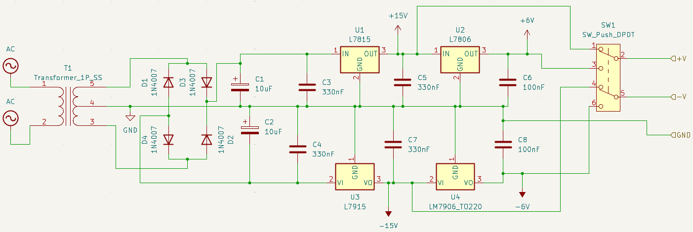
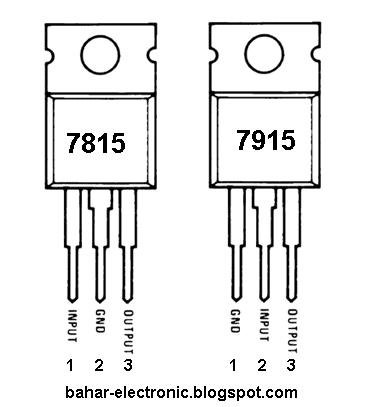
An important detail: pay attention on voltage regulators’ terminals, because 78xx and 79xx don’t follow the same order.
This video shows the modified power source.
